  The ESSB Audio Forum Where all your Hi-Fi Audio Questions are Answered |
 |
 
  |
The ESSB Audio Forum Where all your Hi-Fi Audio Questions are Answered |
|
|
- Mod Notes -
They're a few other things We would like to say.
Difficulty -
First, these mods aren't all that easy if you've never had any SMD (Surface Mount Device) experience.
You run the risk of lifting circuit traces, overheating components, damaging ESD sensitive devices, and such.
Kenwood epoxies there chip components to the circuit boards with glue.
This makes it that much more difficult to desolder and remove these components without damaging the surrounding items.
It takes time, equipment, and patience to do it correctly.
Changing Tantalums and Ceramic Chips with Electrolytics -
What we did was replace the Tantalums (and some other chip caps) with High Grade Panasonic Low ESR Electrolytic Capacitors.
The problem with that is, since the Tantalums are on the bottom of the boards, there's no room for the electrolytics there.
The solution is to carefully drill holes thru the PC board to allow the leads to go thru from the other side.
This makes the mods more time consuming and dangerous.
You have to be aware of the circuit traces on the other side of the board before you drill.
Sometimes you will be drilling thru the Ground Plane on the opposite side,
this requires counter boring to keep the penetrating leads from touching the ground plane.
Op Amps -
We're firm believers in the Audio differences between Op Amps.
The original Op Amps were upgraded with newer Analog Digital units that have a greater Bandwidth, Slew Rate, and SOUND!!
This is something that is NOT necessary to do in order to get the increased Receiver Bandwidth,
but it does affect the overall depth, resonance, and ambiance of the Audio.
Well...
Now to whats really impotent.
This mod is a real pain in the Keester.
Better get yer Coffee, You'll need it!
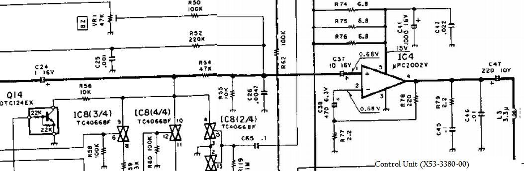
Control Unit (X53-3380-00)
Circuit Description:
AF Amplifier Circuit:
The TS-950sdx uses a separate AF circuit for each receiver (Main and Sub-Receiver) to amplify the Audio Frequencies.
The circuitry for each AF amplifier circuit consists of 3ea pre-amps and and a power amp.
The Control unit receives the pre-amplified Audio from the AF Unit for the start of AF Amplification.
Main AF Circuit
We'll follow the Main AF Circuit first.
The Main AF pre-amplified audio is input to the Control Unit from the AF Unit.
It then goes thru 2ea Tantalum coupling capacitors, (C24 & C37).
C24 is a 1uF cap and rolls off the low frequencies too much. It will be increased in value to 10uF.
C37 is a 10uF cap and slightly rolls off the low frequencies. It will be increased in value to 47uF.
Between C24 and C37 there is also a .0047uF chip capacitor (C26) shunted to ground,
which is rolling the high Frequencies off at around 3Kc.
This cap will be changed to a .001uF cap to increase the cutoff frequency to around 15.9Kc.
The signal is then routed to the Main AF Power Amplifier, uPC2002V (IC4).
The Amplified AF signal then goes thru C47 which is a 220uF Electrolytic.
This isn't near big enough in value. This will be changed to a 1000uf.
The Main AF signal then leaves the Control Unit and goes on to the internal speaker,
Headphone Jack, External Speaker Jack, Remote Jack, and the Phone out Jack.
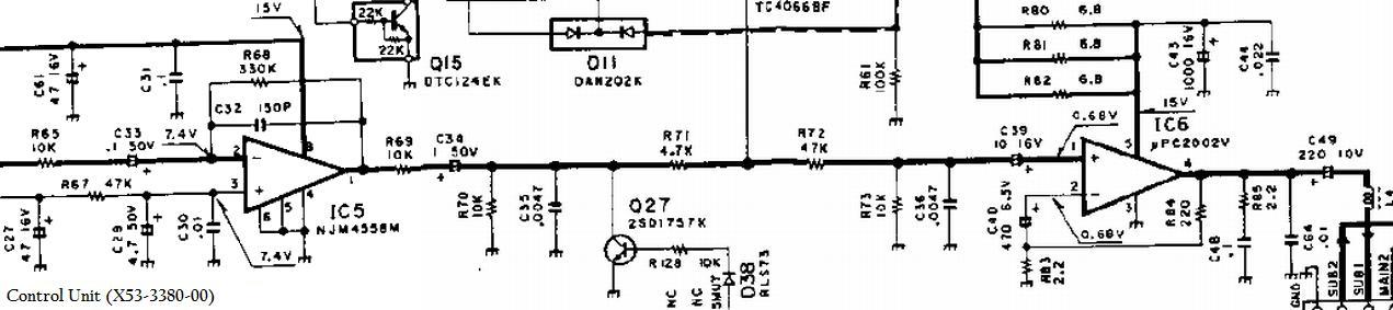
Sub AF Circuit
The Sub AF pre-amplified audio from the 1st Sub pre-amp on the AF Unit, is input to the Control Unit.
The signal then goes to the 2nd Pre-Amp/Low Pass Filter, IC5.
This is a NJM4558M Op Amp configured as an inverting amplifier with a gain of about 31db.
It is using the feedback loop as a Low Pass Filter by paralleling a 150pF chip capacitor (C32) with R68.
The cut off frequency is around 3.3Kc
There are 2ea Tantalum coupling caps (C33 & C34) for this pre-amp which roll off the low frequencys.
We will not be changing the Op Amp (IC5), C33, C34 or C35 as there is no way to widen the 2.1Kc Bandwidth of the Sub-Receiver.
So there is no point in modifying the Audio AF chain after the pickoff for the ACC2 Jack Amplifier on the AF Unit to this point.
The signal then goes by 2ea .0047uF chip capacitors (C35 & C36),
which are shunted to ground and rolling the high Frequencies off at around 3Kc.
C36 will be changed to a value of .001uF to increase the cutoff frequency to around 15.9Kc.
This is being done because Audio from the Main Receiver is mixed in here for the Stereo Receive Function.
We need the Frequency Response wide enough to handle the Main Receive Audio past this point.
C39 is a 10uF Tantalum coupling capacitor and slightly rolls off the low frequencies. It will be increased in value to 47uF.
The signal is then routed to the Sub AF Power Amplifier, uPC2002V (IC6).
The Amplified AF signal then goes thru C49 which is a 220uF Electrolytic.
This isn't near big enough in value. This will be changed to a 1000uf.
The Sub AF signal then leaves the Control Unit and goes on to the Internal Speaker and Headphone Jack.
![]()
Go get them PARTS!!!
Control Unit (X53-3380-00) Mod Parts |
||
Capacitor Value Changes: |
DigiKey - Part Numbers - Panasonic |
|
| C24 - 1uF changed to 10uF 1206 Tantalum to Electrolytic |
P10316-ND ---- EEU-FC1H100L |
|
| C26 - .0047uF changed to .001uF 805 SMD |
PCC102CGCT-ND ---- ECJ-2VC1H102J |
|
| C36 - .0047uF changed to .001uF 805 SMD |
PCC102CGCT-ND ---- ECJ-2VC1H102J |
|
| C37 - 10uF changed to 47uF 6032 Tantalum to Electrolytic |
P10321-ND ---- EEU-FC1H470 |
|
| C39 - 10uF changed to 47uF 6032 Tantalum to Electrolytic |
P10321-ND ---- EEU-FC1H470 |
|
| C41 - 1000uF Electrolytic - (See Note 1) |
P10253-ND ---- EEU-FC1C102 |
|
| C43 - 1000uF Electrolytic - (See Note 1) |
P10253-ND ---- EEU-FC1C102 |
|
| C47 - 220uF changed to 1000uF Electrolytic |
P10253-ND ---- EEU-FC1C102 |
|
| C49 - 220uF changed to 1000uF Electrolytic |
P10253-ND ---- EEU-FC1C102 |
|
| NOTE: 1 As stated in the Text, You will have to use NEW capacitors for C41 & C43, which have longer leads and are smaller in diameter. This is to be able to reposition them on the board to allow room for C47 & C49. |
||
Ummm, which board is it?
Yer gunna have to definitely get to the board and remove it from the radio in order to do these modifications.
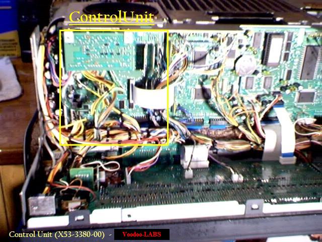
The Control Unit is located in the front of the radio, behind the drop down front face.
It is a Major Pain to get in and out!
To access it, you must take off both the Top and Bottom Covers.
It is best to take the bottom cover off first due to the speaker being in a precarious spot.
Very carefully turn the TS-950SDX upside-down on a clean towel to prevent scratches.
The DSP Unit (normally on the bottom) will be on the top now.
Squeeze the DSP Cable connectors and carefully jiggle them while pulling to disconnect them from the back of the rig.
Remove the 14ea countersunk screws from the bottom cover, then remove the bottom cover.
Carefully turn the rig upside-up o the towel.
Remove the remaining 4ea screws and remove the Top cover.
Face the front of the rig toward you, with the front a little over the edge of the table.
Be sure the towel is hanging over the edge of the table too, to prevent scratches.
This will allow the front to drop down.
On the sides of the front panel you will see 4ea screws (2ea on a side).
Loosen the bottom screws but don't remove them. Remove the Top screws.
You may now slide the Front Panel toward you and it will hinge down revealing the boards.
The Control Unit is the circuit board all the way on the left. See Pic.
There is another circuit board hanging in front of it that must be removed to gain access.
Remove the 2ea screws and place it out of the way.
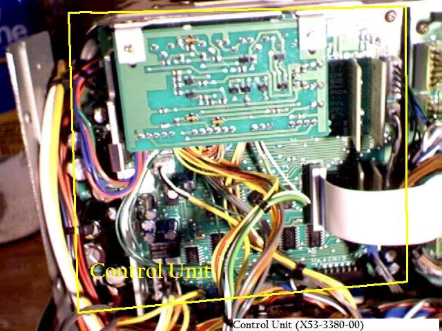
Control Unit Removal:
This Control Board needs to be removed.
We found it's best to remove the Cable Connectors and Ribbon cables first, before the screws are removed.
It might be helpful to take a picture of it, or to label the connectors to aid in reinstallation.
To remove the Cable Connectors, it takes a gentle but firm touch.
Grab the wires next to the connector and lightly pull on it while gently rocking the connector back and forth.
Do this while simultaneously holding the printed circuit board down.
Be very careful not to get to rough with them. You don't want to pull or push too hard, this stuff is fragile.
There is a connector that goes to the Headphone Jack Unit, be very careful with this one!
The Ribbon cable connectors have a quick release on them.
There's a ledge on the top of the connector, gently lift up on the ledge and the top will pop up releasing the ribbon cable.
Remove the screws holding the circuit board in the chassis.
Gently wiggle the board out from under the wire bundles and structure.
Control Unit MODification
Tip #1:
There's a conformal coating on the surface of the PC Board to keep moisture and such from getting to the components and solder pads.
This must be removed before heat is applied.
If it isn't, then you run the risk of it flowing in with the solder and contaminating an otherwise good solder joint.
They're expensive chemicals made just for this application, But we've been using Acetone on a Q-Tip for years with no adverse consequences.
It also works great for cleaning the Flux up after the soldering is finished.
Tip #2:
Un-Soldering can be a real pain in the butt.
They're many special devices just for this.
The thing we use the most of is Fluxed Solder Braid.
This stuff is worth Gold, especially when working with SMD stuff.
We usually fold it in a "V" shape and place it on one side of the SMD solder pad.
Then the soldering iron tip is placed in the "V" and pushed against the solder joint.
Presto...the solder is gone. Then the other side is done.
The SMD will still be stuck there because it is Epoxy Glued in place.
Most of the time when unsoldering the other side of the SMD, while its still hot, you can "flip" it up with the soldering iron tip.
You have to be sure all the solder is gone, cause if it aighnt, you'll lift the solder pad.
One friend of ours says he just takes nippers and crushes the center of the old SMD component while
its still soldered on the board, then unsolders the ends.
Solder Braid also works great on the Plated Thru holes in the circuit board. Like were the Electrolytics are mounted.
Take a small bit of solder and "reflow" the old solder joint.
Then make the "V" with the braid, and apply the soldering iron tip. It will suck all the solder out of the hole.
Most of the time...;)
Tip #3:
For soldering we use an ultra fine tip and a thin solder.
This allows us to get in some very congested areas with the minimum of heat and solder to get the job done.
The size of the solder we use is .025" diameter flux core.
Modify It!
Now that the Control board is out and on the bench, ya got all your parts, ya ready to commit Heresy!
This board is a PAIN to mod.
Most of the components that have to be changed are SMD Tantalum and SMD Ceramic caps.
This mod is a little difficult to explain, but we'll give it our best shot.
Hopefully with the pictures you'll get a good understanding.
Good Luck! ;)
Electrolytic Caps:
The board is marked with both the Capacitor Numbers and the Polarity.
It's really just a matter of unsoldering and removing the old capacitors, and installing the new ones.
But of course there is a Twist on this board!
The sizes are NOT the same so they only fit with some rearranging.
Surprise!
The two we're speaking off is C47 and C49.
The 1000uF are allot bigger in diameter than the 220uF.
There are two other close capacitors (C41 and C43) that physically wont let them fit were they need to.
These are also 1000uF caps.
So what do we do?? You ask.
Well, Remove all 4 caps (C41, C43, C47, & C49)from the board.
You will then install C47 and C49 1000uF capacitors first.
You will probably have to slightly "Dogleg" one of the leads on each capacitor to get it to fit in the holes.
In order to reinstall C41 & C43, you will have to use NEW capacitors which have longer leads and are smaller in diameter.
You will have to "Dogleg" the leads on these a pretty good bit to get them to fit.
It is wise to install spaghetti tubing over the exposed leads to prevent accidental shorts. See Pic.
Be sure to install the Capacitors with the correct Polarity!!
You might notice that C38 and C40 were removed and changed in the pics.
We removed them for ease of modifications, and changed them to increase the working Voltage value.
This is not necessary for you to do.
| C41 - 1000uF | - Change this to a 1000uf |
| C43 - 1000uF | - Change this to a 1000uF |
| C47 - 220uf | - Change this to a 1000uf |
| C49 - 220uf | - Change this to a 1000uF |
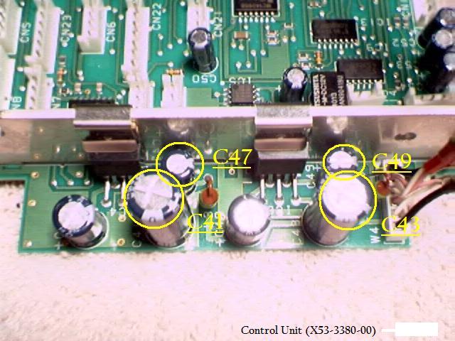
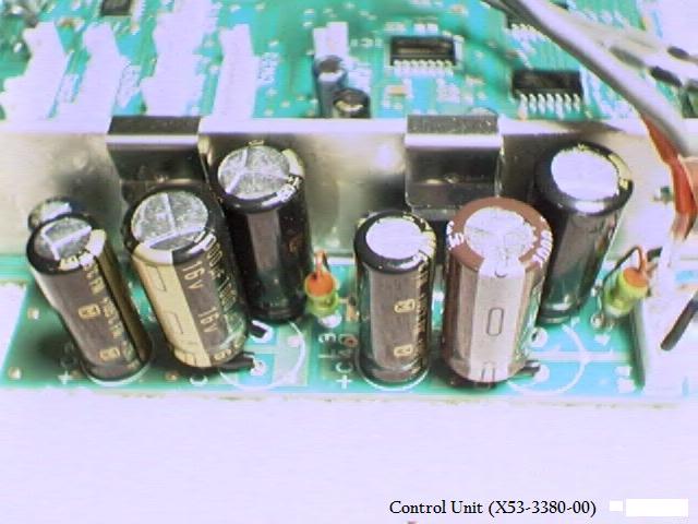
Here is a pic of the Unmodified Control Unit
Notice the lack of room for the bigger Electrolytics at C47 & C49.
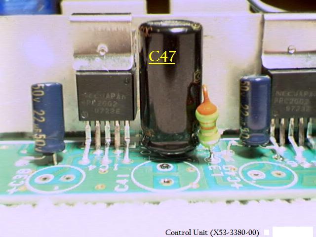
This is C47 installed.
Notice its diameter eclipses the position for C41.
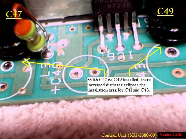
This is C47 & C49 installed.
This is a better pic to show the eclipsed positions for C41 & amp;C43.
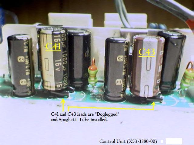
Here's a pic of all the caps installed
Notice the "Doglegs" and the Spaghetti Tubing installed on C41 and C43.
Here's another pic of all the caps installed
Notice the "Doglegs" and the Spaghetti Tubing installed on C41 and C43.
SMD Chip Caps:
These are a little more difficult to identify. The board isn't marked for these items.
We have added some pics to help you find C26 and C36.
Removal and Installation is also a little tricky, especially for beginners.
C24, C33, C34, C37, & C39 are of a special installation and will be described in-depth below.
These 2 chip caps have the same case sizes, so they should fit with no problems.
See the pictures below for the locations.
| C26 - .0047uF | - Change this to a .001uf |
| C36 - .0047uF | - Change this to a .001uf |
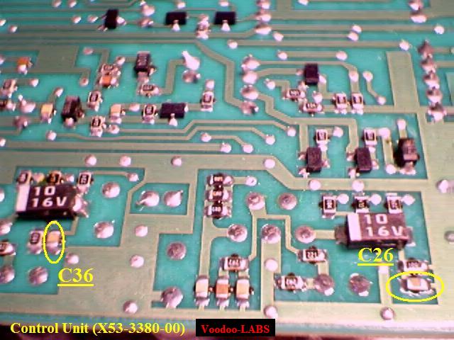
Here is a Pic of the bottom of the Control Unit. The Caps to be changed are marked in yellow.

This is a close up of where C36 is located.
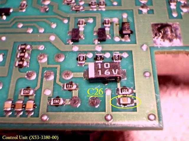
Here is a close up of where C26 is located.
Changing Tantalum SMD Chip Caps C37 & C39:
Here are some pics to help you locate and change C37 and C39 to Electrolytic caps.
When installing the Electrolytics, the "+" terminals must be installed towards Pin #1 of IC4 & IC6!!
| C37 - 10uF | - Change this to a 47uF Electrolytic |
| C39 - 10uF | - Change this to a 47uF Electrolytic |
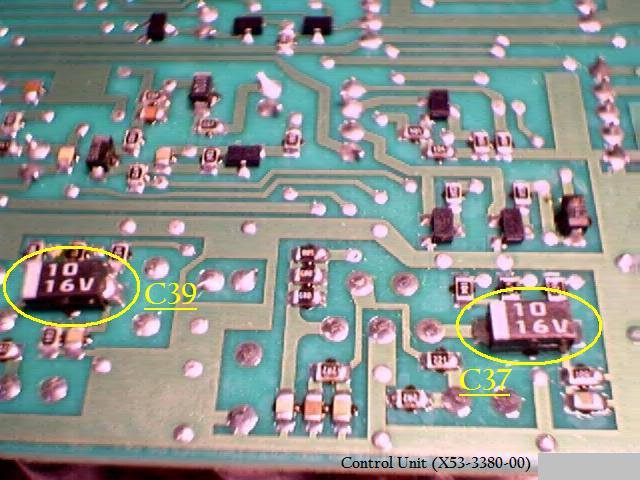
Here is a Pic of C37 and C39 on the bottom of the Control Unit.
The Caps to be changed are marked in yellow.
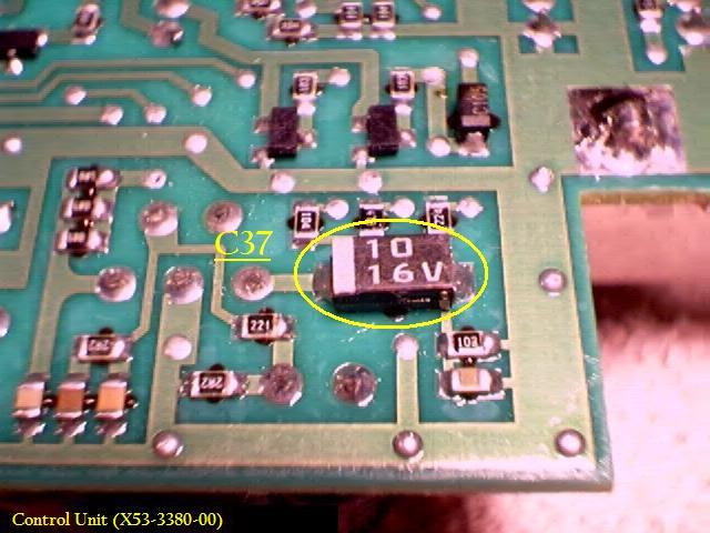
This Pic shows a close up of C37. It is marked in Yellow.
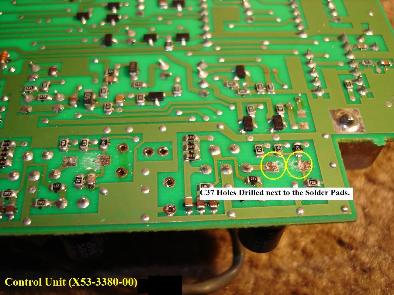
This Pic shows were to drill the Holes thru the Board. They are marked in Yellow.
It is best to use a Pin Vise with a very small Drill bit. We used a .027" bit.
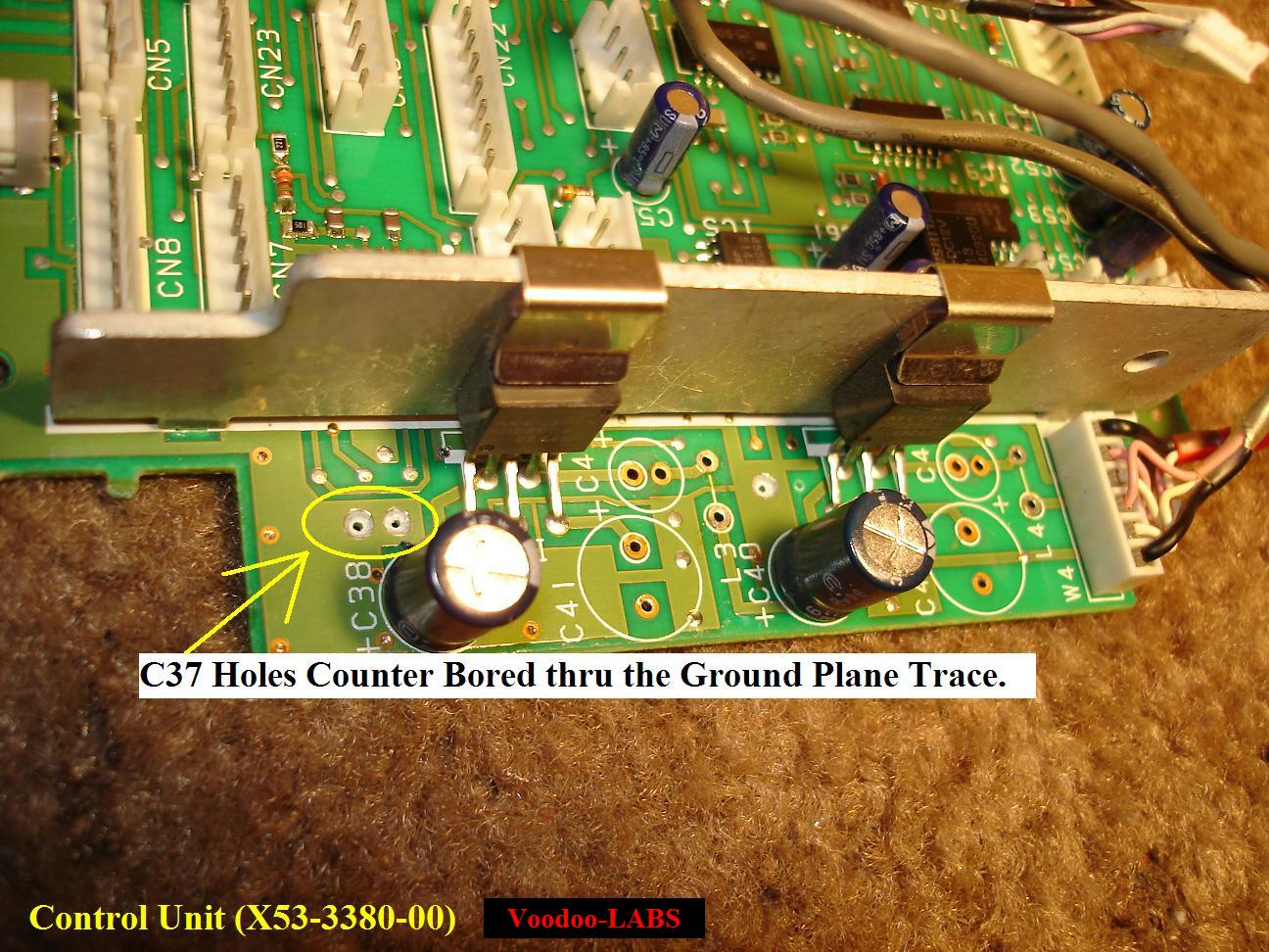
Here's a pic showing the other side of the Control board were the holes come thru.
We had to counter bore them with a bigger bit to prevent the cap leads from touching the Ground Trace.
We install short pieces of heat shrink tubing on the Capacitor leads upon installation 'Just in Case'.

This Pic shows a close up of C39. It is marked in Yellow.
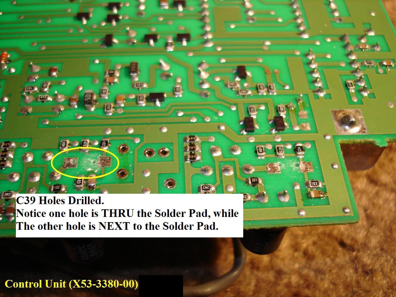
This Pic shows were to drill the Holes thru the Board. They are marked in Yellow.
Notice that the right hole is to be drilled just to the left of the solder pad.
This was done to prevent drilling to close to the solder trace "T" on the other side of the board.
The left hole was drilled thru the Solder Pad.
It is best to use a Pin Vise with a very small Drill bit. We used a .027" bit.
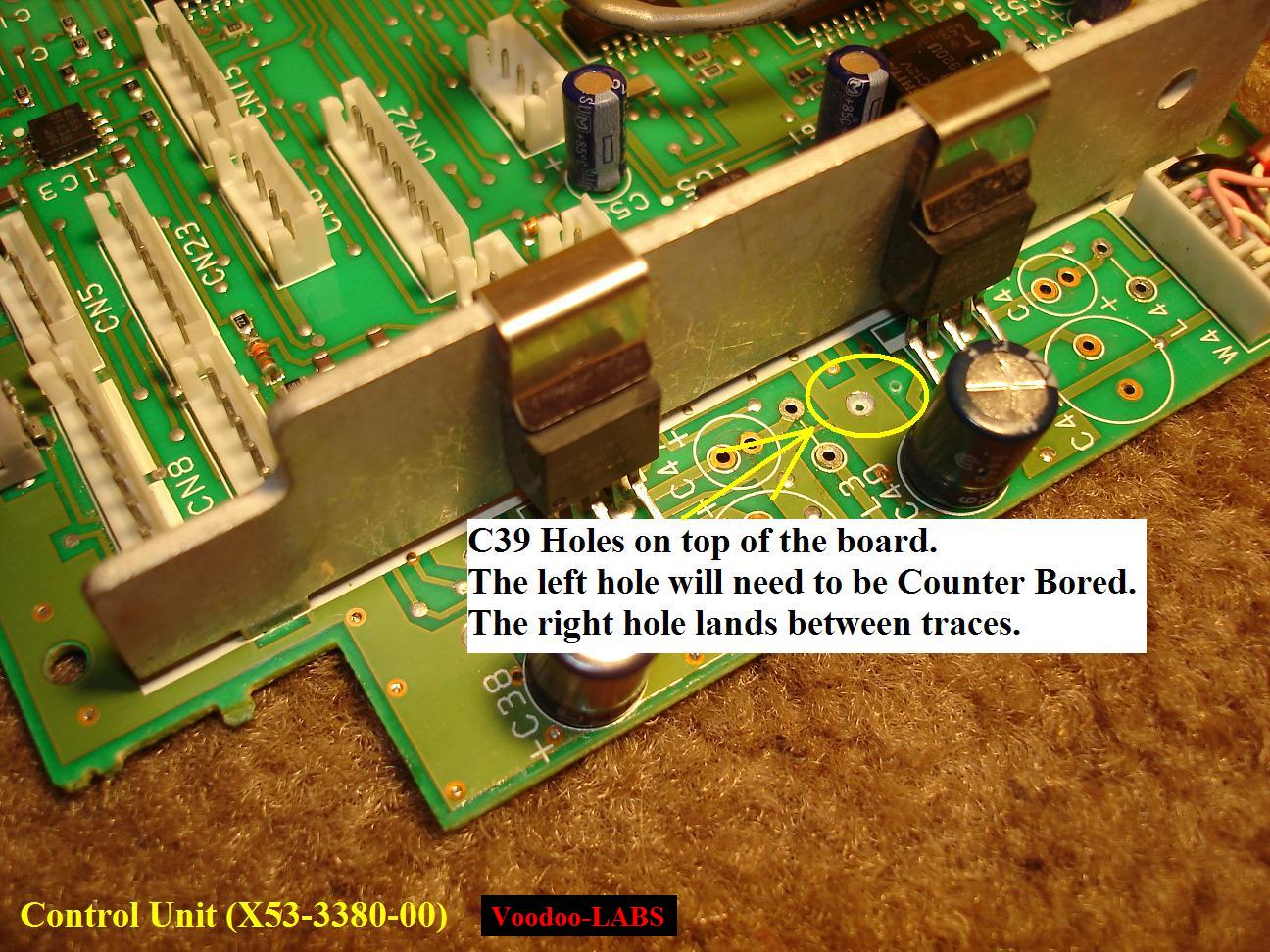
Here's a pic showing the other side of the Control board were the holes come thru.
The Left Hole will need to be Counter Bored. The Right Hole lands in-between the traces.
We install short pieces of heat shrink tubing on the Capacitor leads upon installation 'Just in Case'.
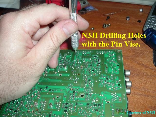
Here is N3JI demonstrating the use of the Pen Vise.
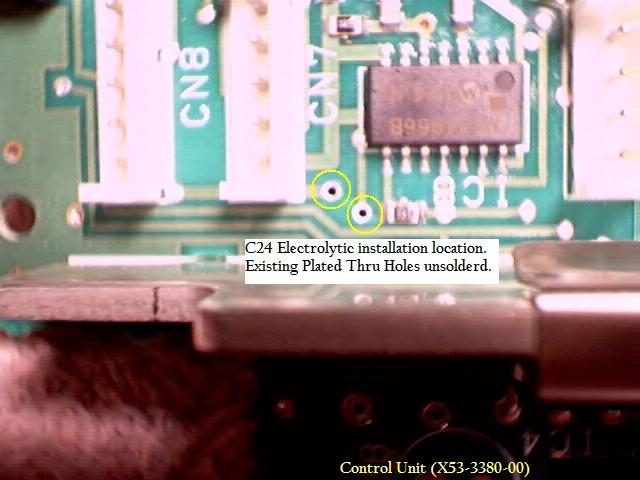
Changing Tantalum SMD Chip Cap C24:
Here are some pics to show you how to change this cap.
When installing C24, the "+" terminal must be installed towards R56!!
| C24 - 1uF | - Change this to a 10uF Electrolytic |
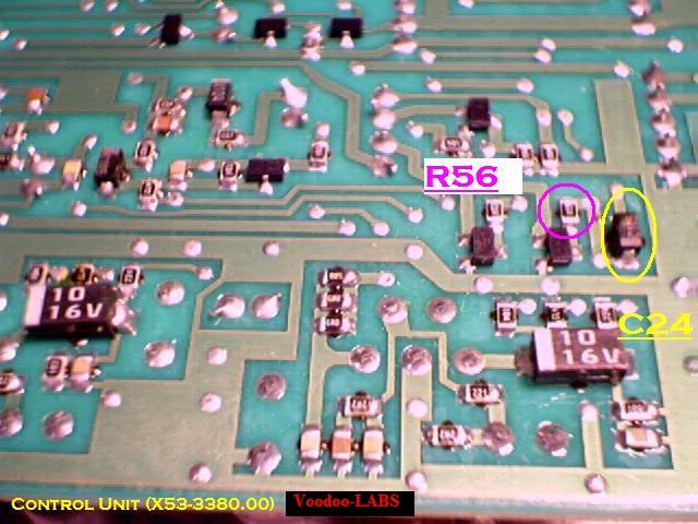
Here is a Pic of C24 on the bottom of the Control Unit.
The Caps to be changed are marked in yellow.
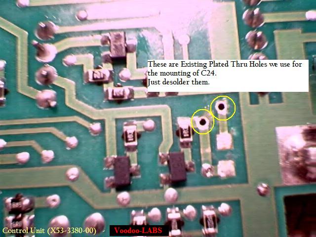
This Pic shows which Plated Thru Holes to use for C24. They are marked in Yellow.
Note that these holes are existing Plated Thru Holes filled with solder.
No drilling is required here, just unsoldering.
Here's a pic showing the other side of the Control board after the Plated Thru Holes were unsolderd.
Control Unit Re-Installation
OK...
Before you attempt to re-install the Control Unit, take the time to look over the board extremely well.
Be sure all the Flux from your soldering is cleaned up.
Look for any accidental solder bridges that might have happened while you were soldering.
Be sure all the cut leads from the installed components are not "stuck" on the board anywhere.
Give it a good inspection.
Control Unit Installation:
It is basically just the opposite of the removal.
We found it's best to install the screws first before the Cable Connectors and Ribbon cables are reattached.
Use the pictures you took of it, or the labeled connectors to aid in reinstallation.
To install the Cable Connectors, again, it takes a gentle but firm touch.
Line up the connector and gently push down on it until it snaps into place.
Do this cautiously, because if you push too hard, you run the risk of cracking the PC Board.
The Ribbon cable connectors have a quick release on them.
Be sure the ledge on the top of the connector is lifted up.
Insert the ribbon cable, then push the ledge down and bottom it out.
NOTE:
We would suggest that you re-install the covers and try the rig out now, before any other modifications.
Do this after each board is modified. This will help you isolate any problems that you might have.
If you modify all the boards at the same time and then have problems it will be more difficult to troubleshoot and fix!
![]()
Congratulations!!
You've just completed a Maniacal Act on the poor defenseless Control Unit!!
The Kenwood Purist's Hunter/Killer Teams are looking for you as you read this!
Hey....let them listen to your new Fidelity!
Click here to Return to the Top of this Page.
Click here to Return to the TS-950SDX Receiver Mods Page.
Click here to Return to the TS-950SDX Voodoo Mods Page.
Click here to Return to the Home Page.
"TS-950sdx Control Unit Mod" page designed by the VOODOO GURU