  The ESSB Audio Forum Where all your Hi-Fi Audio Questions are Answered |
 |
 
  |
The ESSB Audio Forum Where all your Hi-Fi Audio Questions are Answered |
|
|
TX Audio Mod Parts |
||
Parts |
Part Numbers |
|
| Jensen 4:1 Input Transformer | Jensen ---- JT-10KB-D |
|
| Switchcraft 1/4" Gold Plated TRS Jack | http://www.onlinecomponents.com ---- MN112BX |
|
| C152 - 1uF changed to 4.7uF Electrolytic on Signal Unit |
Digikey - P10315-ND ---- EEU-FC1H4R7 |
|
| Mix #31 Ferrite Bead | Fair-Rite ---- 2631540002 |
|
| RG-174 Coax | Belden ---- RG-174/U |
|
| 47uF SU series Bi-Polar - 1ea Needed Electrolytic Capacitor |
Digikey - P1179-ND ---- ECE-A1EN470U |
|
| .01uF - 1ea Needed Radial Lead Capacitor |
Digikey - BC1146CT-ND ---- K103Z15Y5VE5TL2 |
|
| 51 ohm - 1ea Needed 1/4 watt Axial Resistor |
Digikey - P51BACT-ND ---- ERD-S2TJ510V |
|
| 3.6K ohm - 1ea Needed 805 Chip Resistor |
Digikey - RR12P3.6KDCT-ND ---- RR1220P-362-D |
|
| 3.6K ohm - 1ea Needed 1/6 watt Axial Resistor |
Digikey - 3.6KEBK-ND ---- CFR-12JB-3K6 |
|
| 2.4K ohm 1/6 watt Axial Resistor |
Digikey - 2.4KEBK-ND ---- CFR-12JB-2K4 |
|
What do you mean...Drill a 3/8" Hole??!!
Yes, Yer gunna have to drill a 3/8" hole in the back of the rig to do this modification.
Or...another option could be the use of a Greenlee Chassis Punch if available.
This is to mount the Switchcraft MN112BX 1/4" Gold Plated TRS Connector for the Rack Line Audio Input.
You will need to gain access to the bottom of the rig.
To access it, Very carefully turn the TS-950SDX upside-down. The DSP Unit (normally on the bottom) will be on the top now.
Squeeze the DSP Cable connectors and carefully jiggle them while pulling to disconnect them from the back of the rig.
Remove the 14ea countersunk screws from the bottom cover, then remove it.
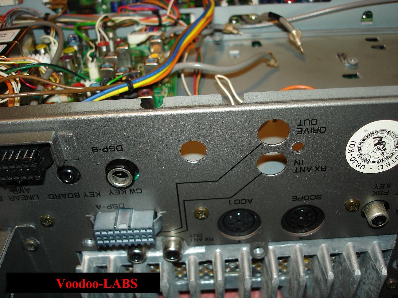
This will expose the inside of the rig. You will see 4ea circuit boards side by side.
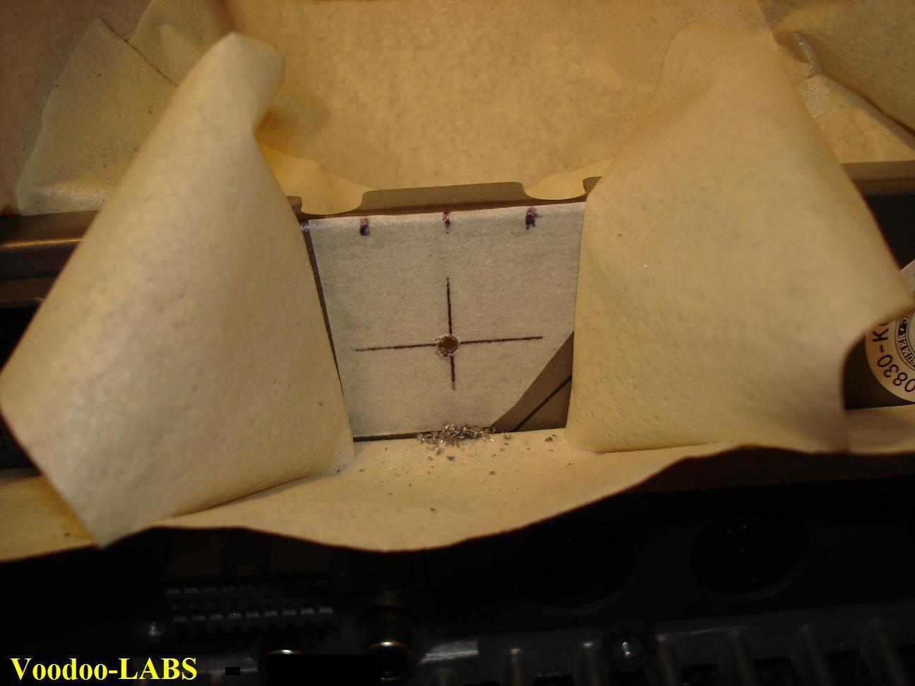
Your target area will be between the two rear circuit boards. See Pic.

We'll describe the "Drilling" procedure as it is rather tricky compared to the chassis punch method.
This is a fairly easy process if you follow some basic procedures, and use the proper tools.
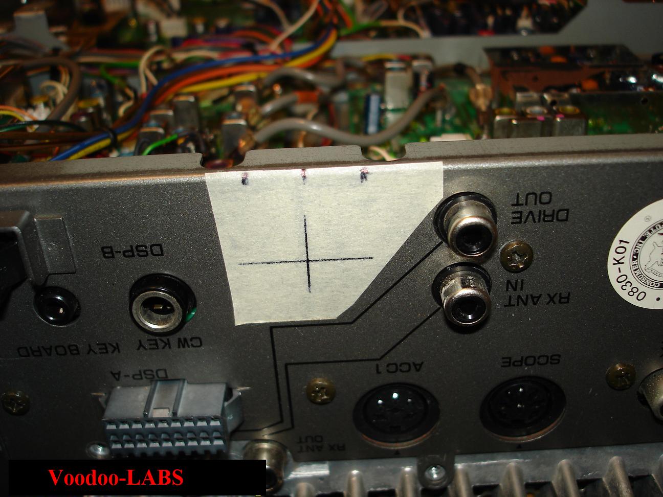
First step is to "Center Punch" the starting hole location.
This is a must and will keep your starting drill bit from "walking" and scratching up the paint.
Another trick to protect the paint, is to place some masking tape over the area.
You'll just drill straight thru the tape.
Eyeball the back and front of the rear panel to be sure you give yourself plenty of clearance for the final 3/8" hole.
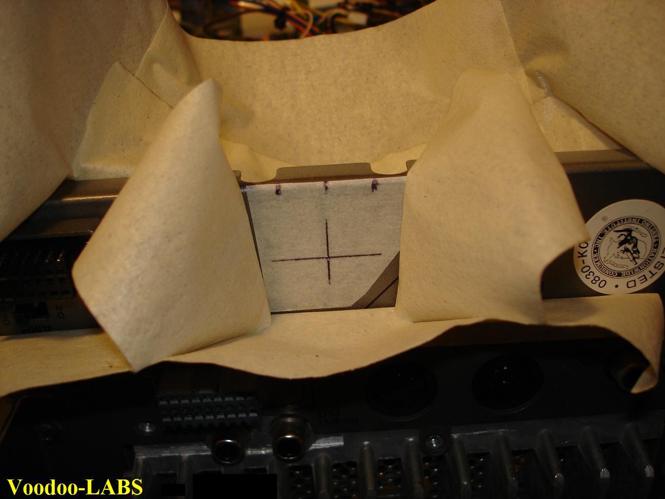
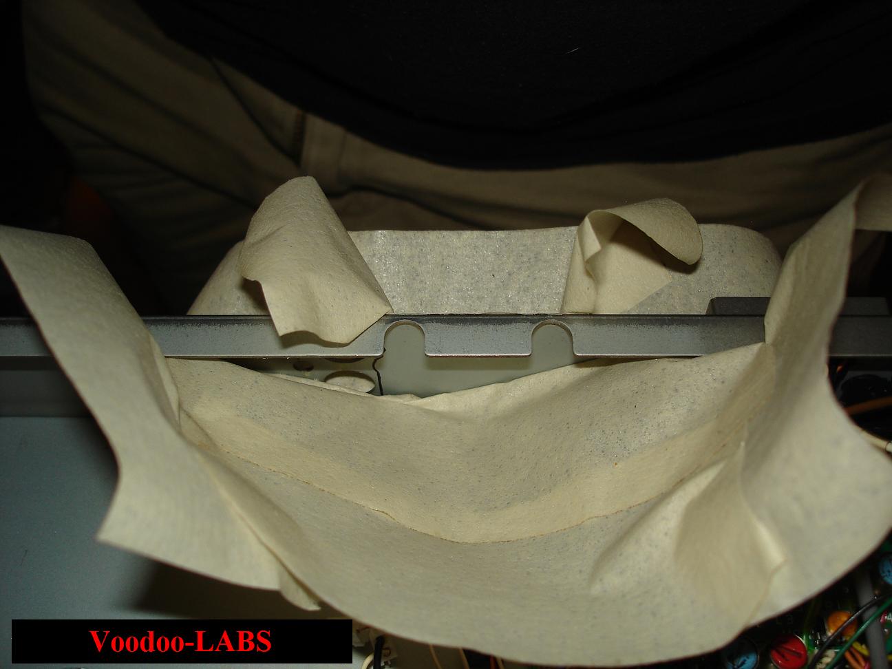
Needless to say, it's a MUST to catch the shavings generated from the drilling operation.
Definitely don't want those nasty conductive buggers down inside your rig.
We used strategically placed pieces of Duct Tape to capture the shavings, see pics.
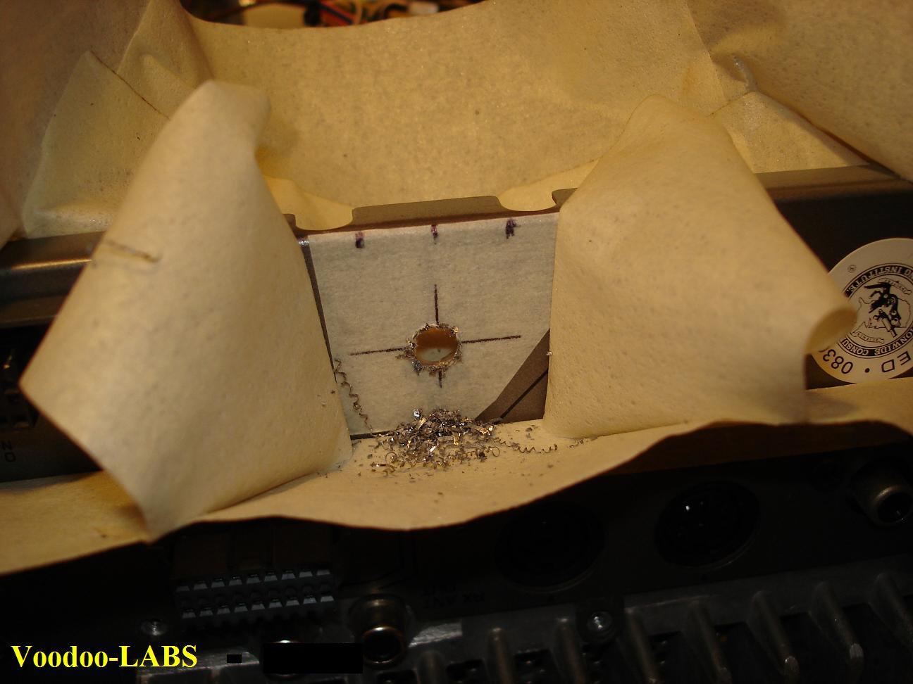
The secret to making a great hole is to step drill. Start with a small bit and progressively go bigger.
Be careful not to go too big (or small) in step size, as the bits will have a tendency to "bite" and "grab"
just before going thru the hole. Especially if using a 2 fluted drill bit.
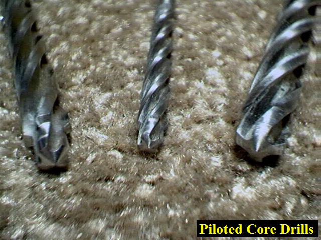
We used a set of "Core Drills" for the final hole sizing.
These bits are a cross between a Reamer and a drill bit. They are piloted 4 flute bits.
They cut beautiful holes, but are very expensive. We got them from our Aircraft Mechanic days.
Use a fairly low speed and light pressure.
Then "deburr" the hole when you reach the final size.
We'd suggest you try this out on some thin sheet metal BEFORE you attempt it on your $2000.00 Radio.
After the Hole is made in the rear of the SDX, now the 1/4" TRS Gold Plated Connector can be installed.
These are fairly hard Switchcraft Connectors to find.
Most distributors don't carry the Gold Plated ones.
I have been getting them from Online Components
There P/N is MN112BX.

The next step is to attach the coax and grounding components.
Jensen suggests to place a 51 ohm axial lead resistor and a .01uf disk ceramic capacitor to
chassis ground from the SLEEVE solder tab of the TRS connector.
Jensen Transformer Installation:
The Line Input Transformer we used, was a Jensen JT-10KB-D 4:1 Step-down.
These can be purchased from Jensen.
We searched for a suitable location to mount the it on the Inside of the SDX.
There really isn't that much room in there!
But we did find a great place to mount it.
Everything is still accessible/removable as it was in stock configuration.
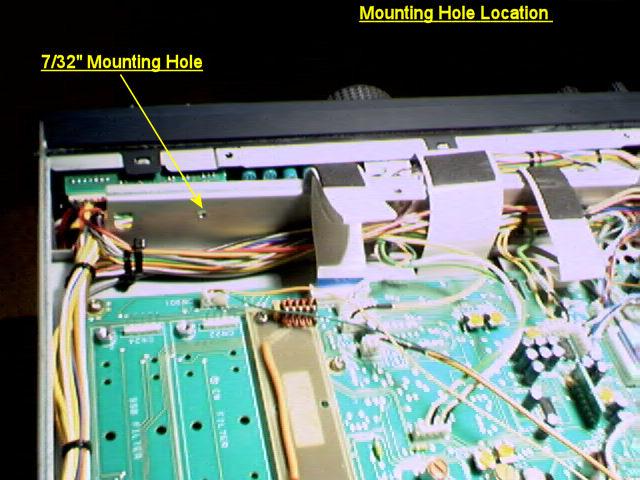
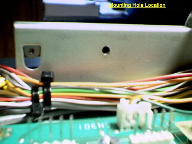
Of course there is a down side (there always is), yer gunna have to drill another hole!
Not a big hole, but it is in a rather bad location.
The Control Unit (X53-3380-00) is going to have to be removed in order to do this.
We drilled a 7/32" hole to install a 10-32 Nylon Mounting Screw with nylon washers and nut.
Be sure to capture the shavings!
The Jensen Transformer must be installed totally insulated from chassis ground.
This is because the SDX Mic Amp circuitry ground is isolated from chassis ground.
This is to eliminate any chance of Hum.
We installed Heat Shrink to our Jensen Xformer to insulate it.
We then used the Nylon Screw, nylon washers, and nylon nut to mount it.
These nylon items were purchased at Home Depot.

You can now mount the Transformer. Leave the wires uncut at this time.
After installation, check the continuity between the Transformer Case and Chassis ground
It should be infinity.
If so, the Control Unit (X53-3380-00) can be re-installed.
Jensen Transformer Wiring and Connection:
With the Jensen Transformer installed in the rig, we can now wire it in.
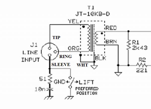
Look below, at the hack job of a circuit schematic we made.
This shows how the Jensen JT-10KB-D Transformer's Input/Output are to be wired and connected to the sdx.

Jensen Input Wiring:
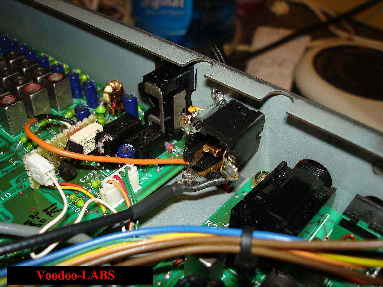
This is were we connect the RG174 coax coming from the TRS connector.
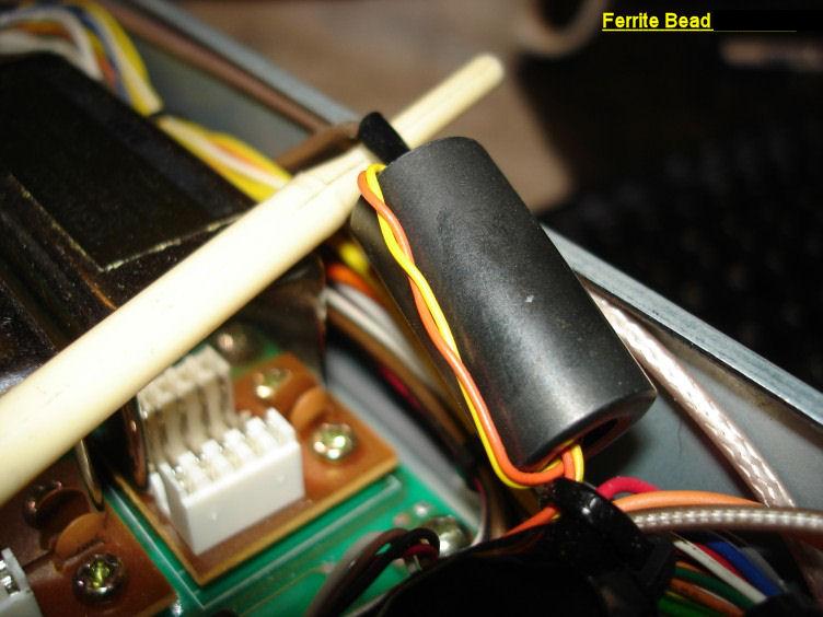
But before the wires are permanently connected, a Mix #31 Ferrite Bead needs to be installed.
This bead is installed close to the Transformer itself.
This is safe insurance to impede any stray RFI from getting into the transformer.
We installed it by looping the Orange and Yellow twisted pair of input wires thru the Ferrite Bead. (see Pic)
The wires are then connected to the RG174.
The Yellow "+" wire is soldered to the center conductor of the RG174, this connects to Pin #2 of the Mini XLR.
The Orange "-" wire is soldered to the Shield of the RG174, this connects to Pin #3 of the Mini XLR.
Jensen Output Wiring:
Jensen suggests installing a 2.43 Kohm resistor across the output of the Transformer for "Perfect Transient" response.
A 2.4 Kohm value is close enough for this requirement.
This Resistor will be installed from the Red Wire to mic ground (Black, Brown , and White wires).
A 47uf SU/Bi-Polar Panasonic capacitor is installed next to isolate the transformer output impedance
from the Mic Gain/Processor potentiometers and other circuit resistance downstream.
We installed the 2.4K Resistor and the 47uf Cap at the transformer,
Encapsulated them in heat shrink tubing,
Then ran RG174 coax to the Mic Amp Circuit Board.
Reference the schematic & pic below.
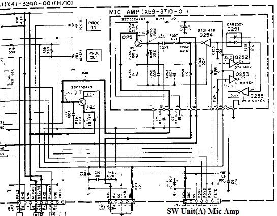
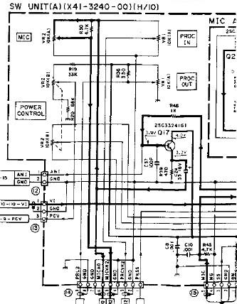
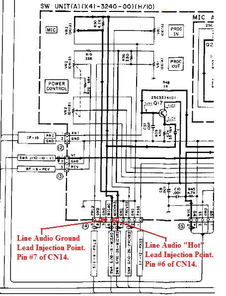
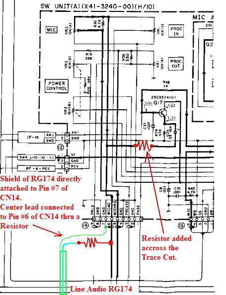
SW Unit (A)(X41-3240-00)(H-10) Mod:
Now it's time to modify the Mic Amp circuitry to accept the Line Audio Input.
After allot of research, We found that the best injection point
would be right before the Mic Gain Control.
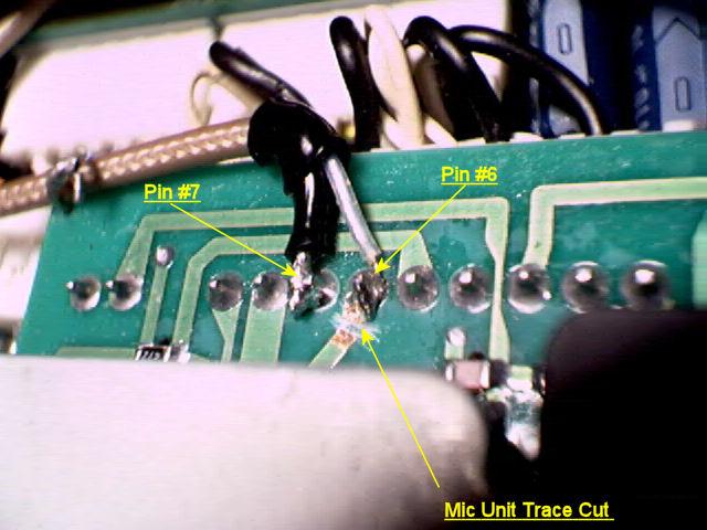
The Center Lead of the RG174 coax was soldered to Pin #6 and the Shield was soldered to Pin #7 of CN14.
This would allow full functionality of all the original Processor, FM, & VOX circuits.
It would also allow for front control gain adjustments for the Line Audio Input.
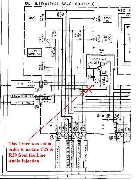
The problem we ran into was that if directly injected at this point,
All the Mid and High Frequency audio energy was being cut.
After investigating this, it was found that C29 and R39 were acting as a RC Filter.
We originally cut the trace leading to these components, and all was well.
The only problem with that, is the loss of the original Mic Audio Inputs.
So, in order to keep the other Mic Amplifier inputs, plus the Line Audio input,
A form of a mixer had to be created to feed both these inputs into the desired injection point.
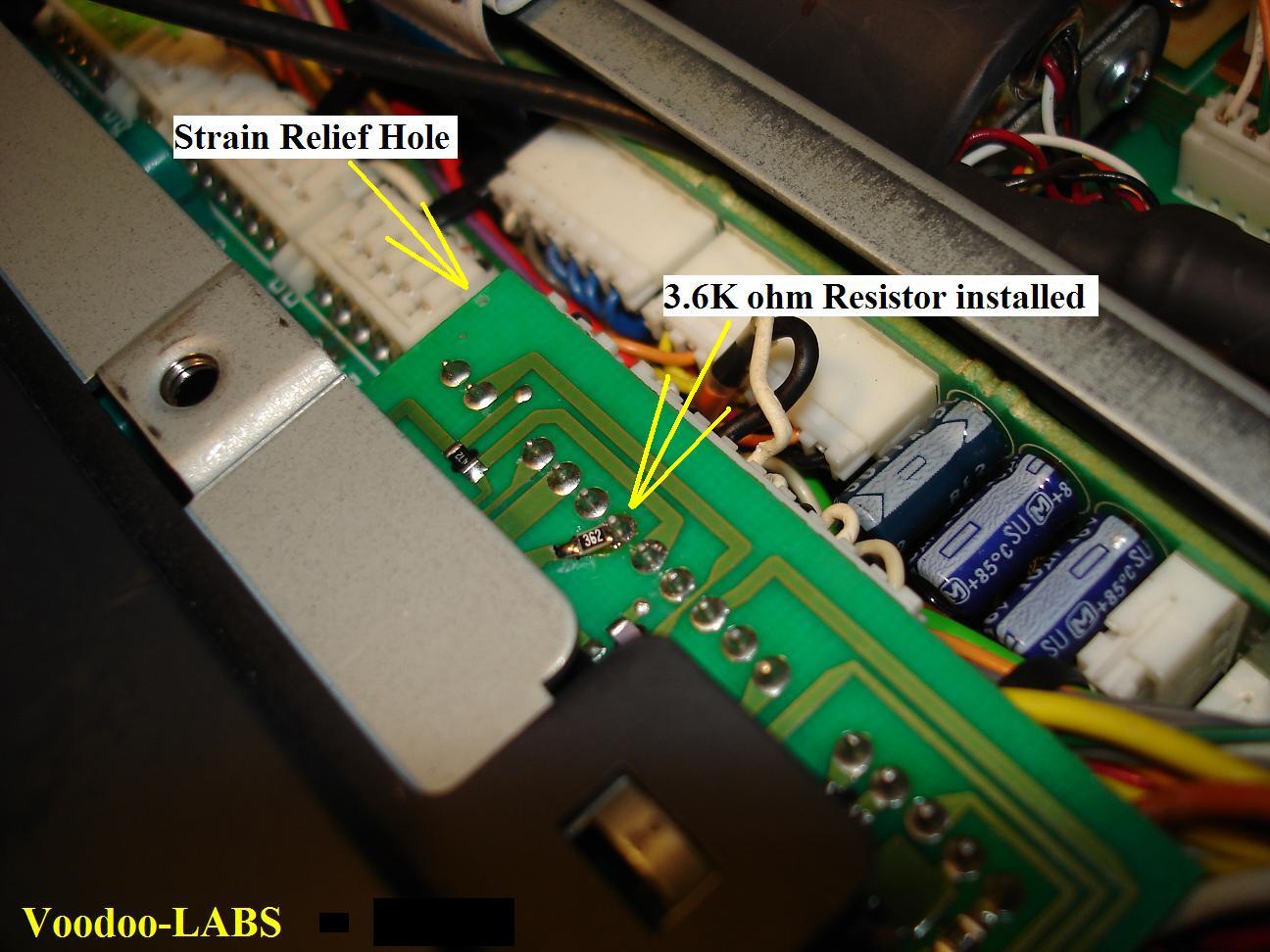
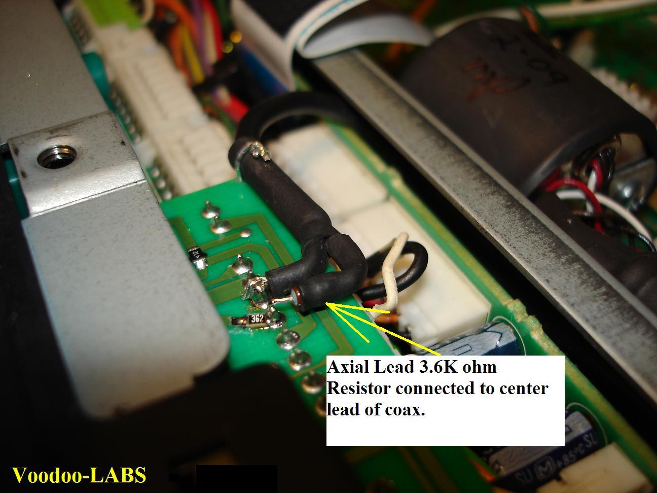
This took the form of 2ea 3.6 Kohm resistors installed at the injection point.
One 3.6K Chip Resistor was soldered in across the Trace that was previously cut,
The other was a 1/6 watt Axial lead resistor soldered in between the RG174 center lead and Pin#6 of CN14.
We also drilled a small hole in the edge of the circuit board in order to
"tie" the coax to the board. This added strain relief for when the front face is tilted forward.

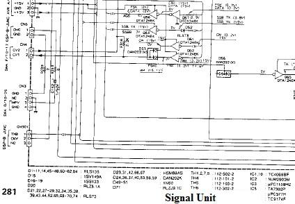
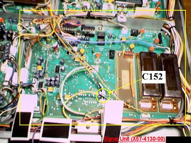
Signal Unit MODification
Yer gunna have to get to the Signal Unit (X57-4130-00) board and
remove it from the radio in order to do this modification.
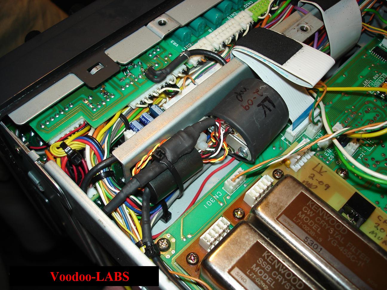
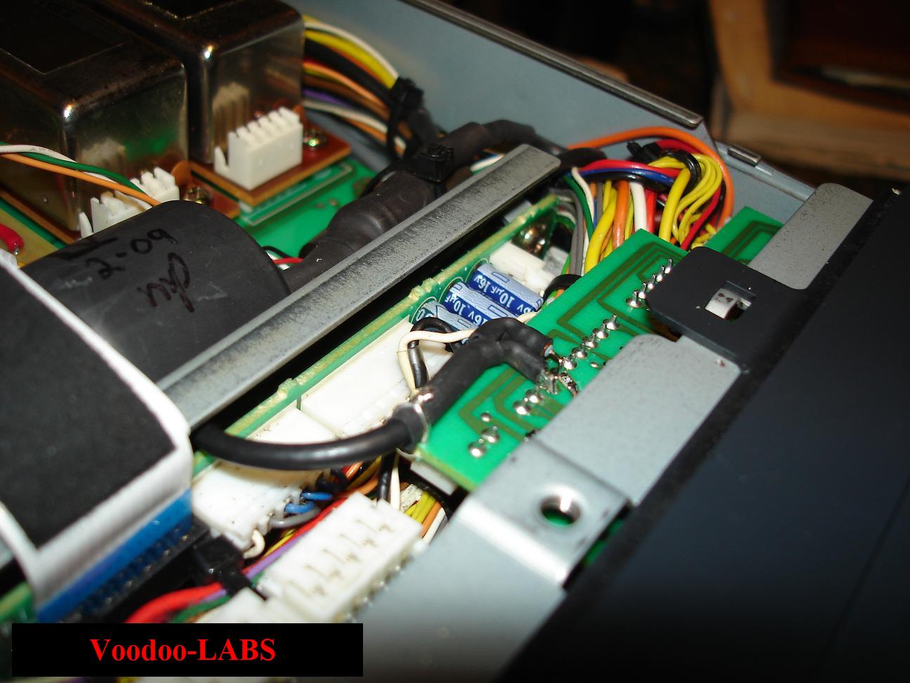
The Signal Unit is located in the bottom of the radio.
With the front of the rig facing you, the Signal Unit is the circuit board on the Right,
closest to you, with the 455Kc Filters on it. See Pic below.
Now that the Signal Unit is out and on the bench,
ya got yer one electrolytic capacitor, ya ready to change it.
Thats right...all that for just one capacitor!!
Well, you could go ahead and do the AM Mods while the board is out of the rig...
only thing is that we don't have them posted yet...Damn it!!!
Electrolytic Cap:
The board is marked with both the Capacitor Number and the Polarity.
It's really just a matter of unsoldering and removing the old capacitor, and installing the new one.
The size is close to the same so it should fit with no problems.
This cap is nestled in between two connectors.
No surprises here.
Be sure to install the Capacitor with the correct Polarity!!
| C152 - 1uF | - Change this to a 4.7uf |
Signal Unit Re-Installation
OK...
Before you attempt to re-install the Signal Unit, take the time to look over the board extremely well.
Be sure all the Flux from your soldering is cleaned up.
Look for any accidental solder bridges that might have happened while you were soldering.
Be sure all the cut leads from the installed components are not "stuck" on the board anywhere.
Give it a good inspection.
The installation is just the reverse of removal.
Be gentle, don't force anything. Double check all the connectors and ribbon cables.
Well, that aught to do it.
You should be able to transmit some very clean audio at a much lower frequency.
Don't forget to wire up the TRS Plugthe same as you did the TRS Jack.
Click here to Return to the Top of this Page.
Click here to Return to the TS-950SDX Voodoo Mods Page.
Click here to Return to the MODification MADness.
"TS-950sdx Transmitter Mods" page designed by the VOODOO GURU