  The ESSB Audio Forum Where all your Hi-Fi Audio Questions are Answered |
 |
 
  |
The ESSB Audio Forum Where all your Hi-Fi Audio Questions are Answered |
|
|
OK,
Now a little word about the circuitry and what we are going to accomplish.
Ground Loops and Digital Noise
Huuuummmm and Buuuuzzzz:
After all the mods were accomplished to the TS-950SDX,
We noticed that there was a slight 60Hz hum in the Audio when the volume was turned all the way down.
This was on both the Main and Sub Receivers, and from every Audio output (Headphone, External Sp, ACC2, etc.).
The worst (loudest) 60Hz hum was in the TX Monitor while Transmitting.
We also noticed a slight Digital type of noise (triple tone buzz) in the Audio when the
volume was turned down and the RF Gain turned all the way up.
Of course this was completly un-acceptable.
So we went on a Hum and Buzz Hunt.
What we found were several circuits in the TS-950SDX that had Ground Loops.
We also found several circuits that were inducing Digital noise into the Audio and IF Circuits.
We have documented this and will show you what traces to cut, connectors to un-connect and/or Shield and so forth.
The hum and digital noise were reduced to imperceptable amounts.
CN109 on the J/10 Switch Unit
This was one of the Major contributors to the Hum Problem.
By breaking the Ground Loop at this connetor solved about 60% of the Hum.
Just follow the pictures below to fix this source.

Here is a Pic of the Switch Unit A (J/10). It is located just in front of the Antenna Tuner.
Un-plug connector CN109 from the Circuit Board.

We use a Razor Blade to slightly flip the keeper up on the connector to remove the Ground Wire.
Then apply Heat Shrink to insulate it.

Reinstall CN109 back into its mateing connector on Switch Unit A (J10).
Monitor Cable Reroute
We found that the Sub Receiver Audio Frequency Cable on the IF Board was
routed too close to the Main Power Transformer electrical field.
The Gain in this circuit is so Hot, that it actually picks up microphonics from the IF Board!
By de-pinning it from CN15 and removing it from its existing wiring harness, then rerouting this
cable perpendicular to the Field of the Transformer seems to have reduced this hum problem considerably.

Remove pins 7 and 8 from CN15 on the IF Unit.

Remove the Sub AF Monitor Cable form its existing wiring harness.
Re-route the cable in the harness as shown in the picture above.

Here is another view of the Harness you re-route the Sub AF cable too.
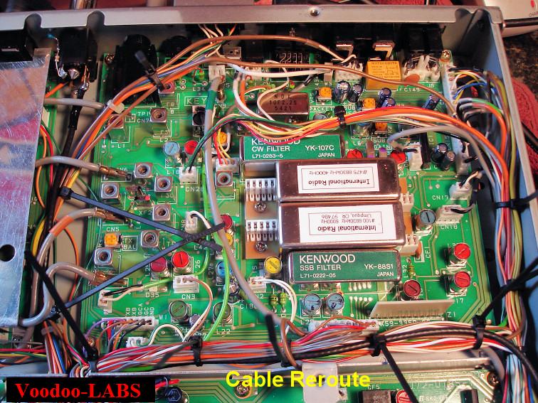
The New Routing of the Sub AF/Monitor Cable.
IF Unit Ground Loop Prevention:
This is another source of 60Hz hum in the Audio of the TS-950SDX.
The fix for the IF Unit is to isolate 3ea Ground Traces from CN15 as shown in the picture below.

Cut the Ground Traces form CN15 of the IF Unit as shown in the picture above.
AF Unit Ground Loop Prevention:
This was were we found another Ground loop problem which was causing Hum in the Sub receiver Audio AF.
The ground at terminal #3 of CN14 of the AF Unit needs to be lifted.
This is accomplished by removing the 0 ohm resistor/jumper, (R301).

Remove R310 on the AF Unit as shown in the picture above.
Digital Noise in the Intermediant Frequency
We found that after the Audio Mods were accomplished and the Receiver was peaked on the TS-950SDX,
there was a low level oscillating multiple digital tone when the antenna was disconnected.
It was discovered that Microprocessor RFI from the Digital Unit was being introduced into the IF Unit.
This was being done through an unused cable harness connecting the two Units.
CN39 at the Digital Unit was originaly used for hard keying CW by the Remote Jack by grounding the signal.
This was abandoned by Kenwood as they are now using the Microprocessor to do this with the RM-1 Controller.
The mating connector CN26 on the IF Unit has the signal terminal floating and not connected to anything.
The broadband Microprocessor RFI is being radiated into the IF circuitry and being demodulated as tones.
The fix is simple, disconnect CN39 from the Digital Unit, insulate, and stow the connector.

Remove CN39 from the Digital Unit.

Heat Shrink CN39 to inslualte it.

Stow the insulated CN39 connector to the wireing harness.
Digital Noise in the Audio
We found that after the Audio Mods were accomplished,
there was a low level buzz when the volume was turned down, and the RF Gain turned all the way up.
It was discovered that Digital AC hash from the Display Unit was being introduced into the Control Unit.
This was being introduced from the AC Power Supply cable harness supplying the Display Unit.
This cable harness runs very close to the inputs for the Final Audio Amplifiers on the Control Unit.
There are two ways to fix this problem, one is to twist the harness and tape it out of the way.
The other is to completly shield the harness and ground only one end at the Power Supply Unit.
Some SDX's are worse then others with this particular noise, so Voodoo-LABS now puts shielding on all rigs .
We unfortunataly do not have any pictures of the shielding procedure at this time.
But we will discribe the procedure...
What we do is pull the sheilding off of a piece of Audio Starquad cable,
Unpin the cable harness from CN6, slide the wires through the shielding,
Attach a drain wire to the Power Supply end of the Shielding, Ground this wire to the Chassis.
Heat Shrink the entire length of the shielding, then Re-pin the connector.
This completely eliminates all the noise.
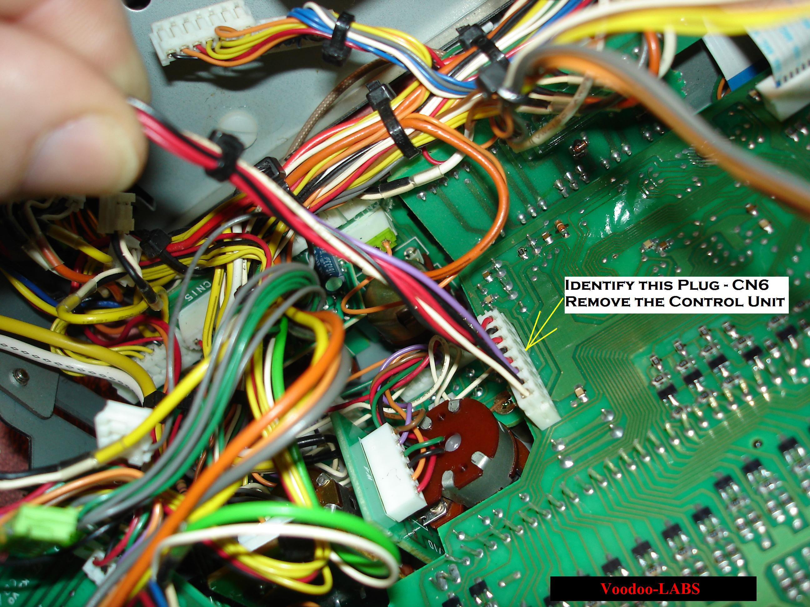
This is CN6 on the Display Unit.
You will need to remove the Control Unit in order to route this harness correctly.

Seperate the CN6 Display Power Supply Harness from the rest of the wires.
Notice the Control Unit is now Removed.

Remove Pins 1, 2, and 3 from Connector CN6.

Put a twist in the wires as shown all the way back to the Power Supply Unit.

Lay the wires directly into the corner of the chassis.
Tape them into position with masking tape to keep them away from the Control Unit.

The remaining wires in that harness were twisted also.
Notice the Control Unit is now re-installed.

The seperated wires are reunited with the main Harness and re-pined into connector CN6.
Route the harness away from the Control Unit and reconnect to the Display Unit.
RFI in the TX Signal
We found that on one TS-950SDX rig, there was some low level RFI present in the TX Signal.
It was found to be coming from the Power Amplifier DC supply cables running with the Local Oscillator coax cables.
There seemed to be a slight amount of RF coming back from the Power Amplifier on
certain Bands that was getting into the Local Oscillator cables and hence into the Transmitted Signal.
This was noticed only on one SDX Unit, but we now accomplish this Mod on all units.
The fix is to remove these PA Supply cables from the Local Oscillator harness,
then reroute and keep them as close to the ground plane as possible.
One Extra thing we did here at Voodoo-LABS was adding a Mix 31 Ferrite to the PA Supply Cables.
You can see in the Picture where it just fits nicely.

You can see how the PA Power Supply Cables and the LO Signal coax are ran away from each other.
The Snap-On Mix31 Ferrite is on the cables to the right of the picture, in front of the Ant Tuner.
Click here to Return to the Top of this Page.
Click here to Return to the TS-950SDX Voodoo Mods Page.
Click here to Return to the Home Page.
"Voodoo-LABS TS-950sdx Hum-Noise-Cable Reroute Mods" page designed by the VOODOO GURU