HHB Radius-20 Audio Modifications
 Voodoo-Labs has designed a Secret Weapon!
The HHB Radius-20 Tube Parametric EQ
Voodoo-Labs has designed a Secret Weapon!
The HHB Radius-20 Tube Parametric EQ
This mutation is a Voodoo Screamin Machine!
These Mods increase the Clarity, Separation, & Smoothness
of the Entire Frequency Spectrum by an incredible amount.
It makes the Audio sound like Ethereal Music.
Disclaimer NoticeThese modifications should be accomplished by qualified personnel who
have had enough knowledge and practice in SMD soldering techniques, at the owners risk.
WARNING - YOU DO THE MODIFICATIONS AT YOUR OWN RISK!We are not responsible for any personal injury incurred while performing these mods.
We are not responsible for any damage to, or illegal operations of the equipment as a result of the
mods, mod errors, or possible mod misinformation via these pages.
The modifications shown here are provided for properly licensed operators only.
The user is solely responsible for making sure that any modifications made to the equipment must meet all
Federal and State Regulations for the Country of use.
Liability of damages to any equipment is the sole responsibility of the user.
Downloading , viewing, or using any information provided on these pages automatically accepts the user to the terms of this agreement.
Modifications are provided for information purposes only.
Although the greatest care has been taken while compiling these documents,
we cannot guarantee that the instructions will work on every piece of equipment.
Copyright Notice
All contents on this site, including text, graphics, and MP3 audio recordings are considered property of Voodoo-Labs and are
protected by copyright law and may not be reproduced or distributed in any way or form, without express written consent or permission by Voodoo-Labs.
Failure to comply with copyright law may result in legal action.
That's Right !!
This unit is now one of our most favorite Weapons of Mass Destruction
and has a permanent place in the rack.
The Audio from it just sings in a way that
brings your Soul to new depths of Existence.
The Audio is so Sublime and Ethereal,
it just doesn't seem right to be in this plain of existence!
HHB Radius-20 Mods
Some Radius-20 Discussion:
We here at Voodoo-Labs have done some extreme modifications to the HHB Radius-20
to get the best resonance and clarity out of it.
This has to do with changing out the Op Amps to a better chips with
higher bandwidth, higher slew rate, and lower noise.
That chip would be the Analog Devices AD823ARZ.
The ARZ is the case designator for a No Lead, Surface Mount SOIC case designation.
That's right....Surface Mount, and this Mod is VERY difficult to do.
There are 16ea of them that need to be changed out.
14ea of them are Quad TL074 (Yuk Spit!!) and 2ea are 5532's.
(The 2ea 5532's are DIP packaged Op Amps and the part number for there replacement is
either the Analog Devices AD823AN or the AD823ANZ).
That means they all need to be removed, and then 16 sockets installed.
The TL074 is a nasty, older technology Op Amp that will distort like MAD if overdriven in the least.
Its Audio in the Low Frequencies is also borderline in quality.
The problem with this Quad Op Amp is there are very few High Performance replacements for it,
and we wanted to use the AD823 Dual Op Amp (It takes 28ea of them!!!).
This problem is overcome with a special converter board that allows any of
the popular dual Op Amps to be retrofitted into a standard quad socket.
We found this unit on Eddie Ciletti's fine website.
There are also allot of coupling caps (39ea) that need to be changed out to
higher quality Panasonic FC series, Low ESR caps for improved audio transfer and sonic signature.
The exception to this are the 4ea 330uf Output Capacitors right next to the 8pin Output Buffer Op Amps (Reference the Pics).
Depending on the version of your HHB, You might or might not have the 'Rubycon' type Capacitors installed.
If you DO have the 'Rubycon', then LEAVE THEM INSTALLED.
If you don't have them, then install the Panasonic FC series caps.
Then there's the Power Supply improvements that help to calm the
transients,
the rectifier over/under shoot during rectification, and some improved filtration.
These improvements all help to give the Op Amps the best DC Voltage for Audio Processing.
All these mods transform this Radius-20 into a Voodoo Music Machine.
The last Mod is 'Rolling' the Tubes.
We used the Sylvania 5751 Government Gold Label, Black Plate tubes with the silver pins.
These are some of the most Musical Tubes we've ever heard here at the Voodoo Labs.
There sound is incredible, but they are VERY rare and VERY expensive when found.
We used them for this EQ because we were looking for the best sound in the Total Frequency Response, not just the Low End.
The next best Tube to use would be the RCA Command Series 5751 Black Plates, then the GE JAN 5751 Gray Plates.
The results from these Mods are incredible.
Now get in there and create some MODification MADness....
MOOOO HOOOO HAAA Haaa haaaa!!!
|
Radius-20 Mod Parts
|
Parts |
Part Numbers |
| 4ea - 330uF @ 25v Electrolytic |
Digikey - P10272-ND ---- EEU-FC1E331L |
| 33ea - 100uF @ 25v
Electrolytic |
Digikey - P10269-ND ---- EEU-FC1E106 |
2200uF changed to 3900uF @ 35v
2ea - Electrolytic |
Digikey - P11249-ND ---- EEU-FC1V392 |
4700uF changed to 5600uF @ 25v
1ea - Electrolytic |
Digikey - P11228-ND ---- EEU-FC1E562 |
| 1ea - 100uF @ 350v Electrolytic |
Digikey - P5938-ND ---- EEU-EB2V101 |
| 2ea - 10uF @ 250v Electrolytic |
Digikey - P5334-ND ---- ECA-2EM100 |
| 4ea - 4.7uF @ 50v Electrolytic |
Digikey - P10315-ND ---- EEU-FC1H4R7 |
| 28ea - AD823ARZ
SMD Op Amp IC |
Digikey -AD823ARZ-ND ---- AD823ARZ |
2ea - AD823AN 8 pin DIP Op Amp
|
Digikey -AD823AN-ND ---- AD823AN
ALT -Digikey -AD823ANZ-ND ---- AD823ANZ |
| 4ea - 600V 4A Hexfred Diode Rectifier |
Digikey - HFA04TB60PBF-ND ---- HFA04TB60PBF |
| 14ea - Gold Plated 14 pin DIP Socket |
Digikey -ED56143-ND ---- 110-13-314-41-001000 |
| 2ea -Gold Plated 8 pin DIP Socket |
Digikey - ED56083-ND ---- 110-13-308-41-001000 |
14ea - GEC-D2Q (Eddie's P/N)
Dual to Quad Converter Board
|
|
Soldering TIPS:
They're a few tricks to unsoldering Op Amps that we'd like to share with you.
Tip #1:There's a conformal coating on the surface of the PC Board to keep moisture and such from getting to the components and solder pads.
This must be removed before heat is applied.
If it isn't, then you run the risk of it flowing in with the solder and contaminating an otherwise good solder joint.
They're expensive chemicals made just for this application, But we've been using Acetone on a Q-Tip for years with no adverse consequences.
It also works great for cleaning the Flux up after the soldering is finished.
Tip #2:
Un-Soldering can be a real pain in the butt.
They're many special devices just for this.
The best way to remove the old Op Amps without special tools, is to take some small sharp nippers and
cut each and every one of the leads on the chip while it is still soldered to the PC board.
Make SURE all the leads are clipped, then pop the old Op Amp off the PC board.
Then take some Needle nose pliers or tweezers and pull each cut lead from its solder hole while applying the soldering iron.
Then go back and use the solder sucker to clean out the holes.
Be Careful to get all the cut leads off of the board.
Then clean up the area with some acetone and a Q-tip.
Presto...the Op Amp is removed and the solder pads are clean.
If the Solder Pump gives you problems, the Solder Braid also works great on the Plated Thru holes in the circuit board.
Like were the Electrolytics are mounted.
Take a small bit of solder and "reflow" the old solder joint.
Then make the "V" with the braid, and apply the soldering iron tip. It will suck all the solder out of the hole.
Most of the time...;)
Tip #3:For soldering we use an ultra fine tip and a thin solder.
This allows us to get in some very congested areas with the minimum of heat and solder to get the job done.
The size of the solder we use is .025" diameter flux core.
Stock Op Amp Eradication!!
There are 16ea Op amps that were changed in this unit.
12ea - 14pin Quad TL074's, and 2ea - 8pin Dual 5532's.
Their all changed so there is no need to list them.
They will all be removed from the PC Boards and Gold Plated Sockets installed in their place.
Be sure to read the Soldering Tips above for the best way to remove the old Op Amps to prevent Circuit Board Damage.
When you install the Sockets, Be SURE to install the Sockets in the correct orientation.
There is a little 'Dip' in one end of the Socket, this is placed where Pin #1 is on the Circuit Board.
There is usually a 'Dip' shown on the PC Board Silkscreen for the IC. Just match the two up.
You'll have to remove the boards completely from the unit.
This is not hard. Just go slow and be aware of what needs to happen before you do it.
Removing the knobs is a little different, reference the pictures for this.
The unit comes apart easily, but must be almost completely disassembled to get the Circuit Boards out.
The Next step is to make the Replacement Op Amps.
Make them???? What??
That's right, make them .... well ... Assemble them anyway.
There are hardly any High Performance Op Amps in the Quad 14pin Package these days.
The only real good ones are either in Dual or Single packages.
Our favorite, the AD823 is only in a Dual Package, so we had to find a way to make them work.
We found a special converter board that allows any of the popular dual Op Amps to be retrofitted into a standard quad socket.
These Cool units were created by Everett Carroll and can be found on Eddie Ciletti's fine website.
It comes as a Blank Converter Board to which you will have to solder 2ea AD823AR SMD Op Amps onto.
Then you must solder a 14pin Gold Plated Header to the Converter Board
(Reference Pics).
This in turn Plugs into the 14pin Gold Plated Sockets.
Be careful, their a TIGHT fit!
Be sure to support the bottom of the PC Board or you might crack it trying to push these dudes in all the way.
Be SURE to install the Op Amps with the correct Pin #1 Orientation to the Converter Board!!
There is a Cheat Sheet that comes with the Boards to show the correct orientation.
Be SURE to install the Converter Boards with the correct Pin #1 Orientation to the Gold Plated Sockets!!
If you don't, you'll make Toast out of 'em.
There's a big 'Arrow' on the Converter Board pointing toward the 'Dip' in the Socket.
REAL SLICK, HUH??!!!
Now that they are changed,
You need to let them burn in for at least 50 hours with a signal going thru them before making any judgments.

Here's the inside of the HHB Radius-20 before any mods. It all needs to come apart!

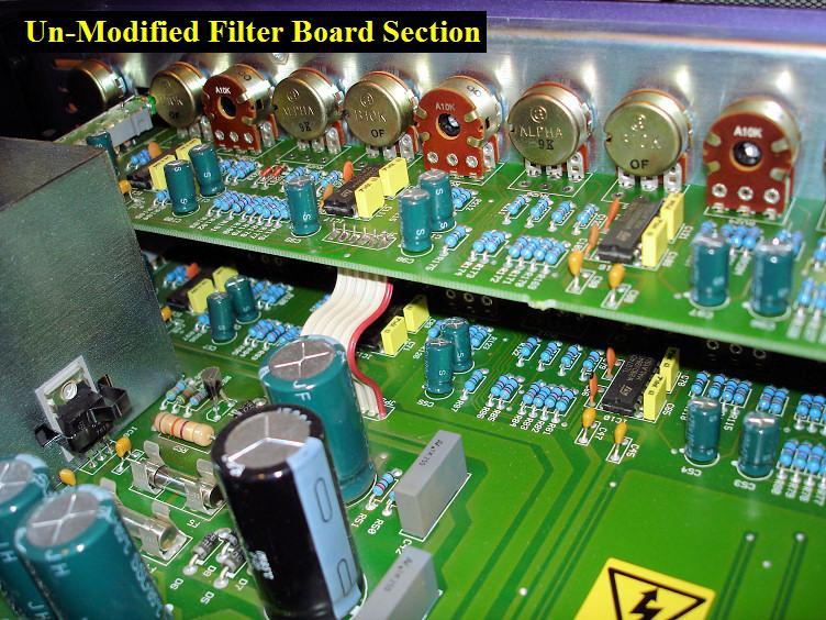
Here's a view of the Filter Boards before they were disassembled and the Op Amps were Removed.
Notice the ribbon cable, that will have to be unsoldered during disassemble as well.
Here's another view of the Filter Boards before they were disassembled and the Op Amps were Removed.
Notice the ribbon cable, that will have to be unsoldered during disassemble as well.
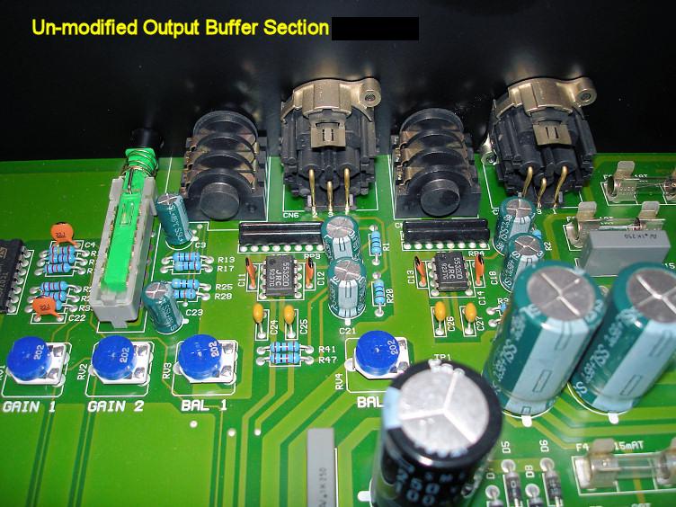
Here you see the un-modified Output Buffer Section on the Main Board.

Here's the un-modified Input Buffer Section on the Main Board.

This is the Tube Section of the HHB.
The caps are not yet changed, but you can see the Gold Label on one of the Sylvania Tubes.
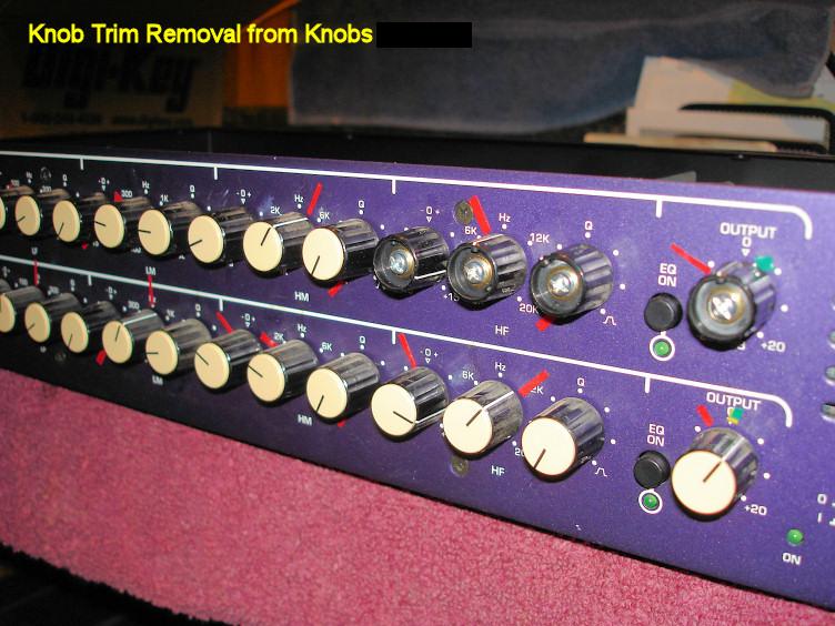
You can see here how the knobs are to be accessed for removal.
Use your finger nail to pop the caps off. If you use something sharp or hard, you'll deface the knobs.
Then unscrew the Compression Clamp Screw a little, the knob will pull right off.
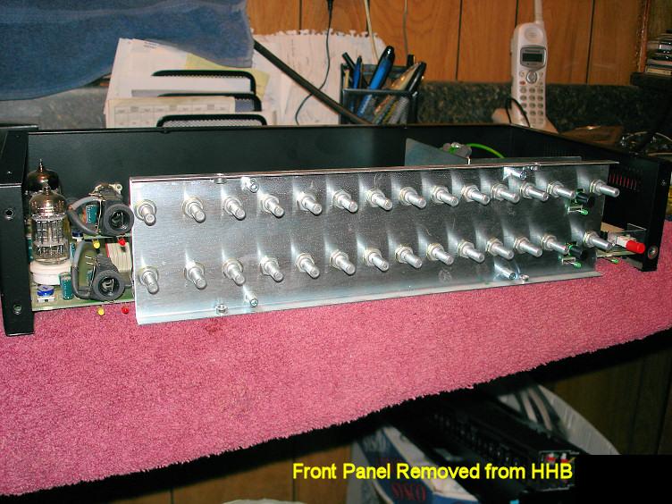
After all the knobs are removed, remove the 2ea Nuts on the 'Instrument Input' Jacks.
Then remove the 8ea Philips screws in the Front Panel. The Front Panel should fall right off.
It's best to unsolder the 2ea Filter Board Ribbon Cables now before you take off the Backup Plate.
Now you must remove all 28 Nuts from the Potentiometer Shafts.
The Backup Mounting Plate should come off now. Be careful of the LED's.

Here is the Top Filter Board out on the Bench.
Now it's time to remove all the old Op Amps and install the 14pin Gold Plated Sockets.
Be SURE to install the Sockets in the correct orientation!!
This is also the time to change out all the Capacitors.
Be SURE to install the Capacitors with the correct Polarity!!
Notice this one already has the Sockets installed...heheheh...Lucky Us!!
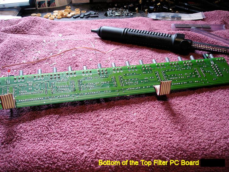
This is a close-up of the Backside of the Top Filter Board for Your viewing pleasure.

Here's the Input Buffer's 14pin, Gold Plated Sockets Installed.
Be SURE to install the Sockets in the correct orientation!!There is a little 'Dip' in one end of the Socket, this is placed where Pin #1 is on the Circuit Board.
There is usually a 'Dip' shown on the PC Board Silkscreen for the IC. Just match the two up.
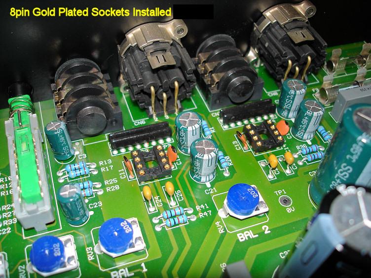
Here's the Output Buffer's 8pin, Gold Plated Sockets Installed.
Be SURE to install the Sockets in the correct orientation!!
There's the 4ea 330uf Electrolytics next to the 8pin Sockets again.
If there not marked as 'Rubycon', they need to be changed with the Panasonic FC series caps.
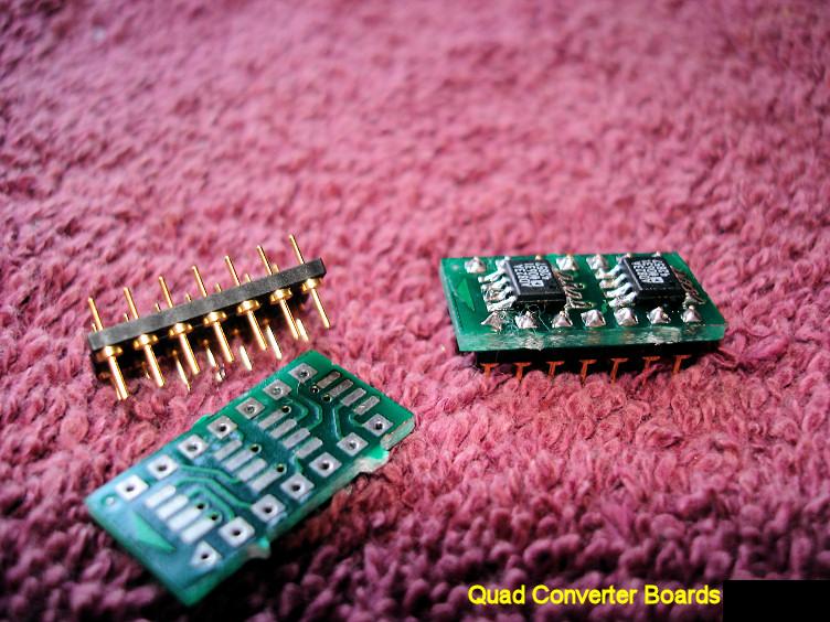
These little Jewels are the Quad Converter Boards.
The AD823's are soldered onto the Converter Board.
Then the Header Pins are soldered to the Converter Board.
Be SURE to install the Op Amps with the correct Pin #1 Orientation!!
If you don't, you'll make Toast out of 'em.
One Down....only 13 more to go!! Ha Ha Ha Ha!!

There All Done!!!Aighnt that Perty!!
Those are some Cool Boards, Thanks Everett!!!!
Electrolytic Caps:
We didn't get elaborate with the info and Capacitor #'s here because
you will be changing almost all of them, except for a few listed below.
Just be sure to note the Polarity of the ones you are removing. The Circuit Boards are marked.
It's best to do just one Capacitor Value Range at a time, that way you don't have to remember where and what.
It's really just a matter of unsoldering and removing the old capacitors, and installing the new ones.
The sizes are close to the same so they should fit with no problems.
No surprises here.
But Be sure to install the Capacitors with the correct Polarity!!
There are some Caps that will not be changed.
1 - There are 4ea 330uf Output Capacitors right next to the 8pin Output Buffer Op Amps. (Reference the Pics)
C5 - 330uf, 25v
C8 - 330uf, 25v
C18 - 330uf, 25v
C21 - 330uf, 25v
Depending on the Serial Number of your HHB, You might or might not have the 'Rubycon' type Capacitors installed.
The word 'Rubycon' will be printed on the side of the cap.
If you DO have the 'Rubycon', LEAVE THEM INSTALLED.
If you don't have them, then install the Panasonic FC series caps.
2 - Do NOT change the Following Caps:
These are for the 'Drive' and 'Peak' LED Circuits, and do not need to be changed because they are not in the Audio Path.
C116 - 4.7uf, 63v
C128 - 1uf, 100v
C74 - 4.7uf, 63v
C129 - 1uf, 100v
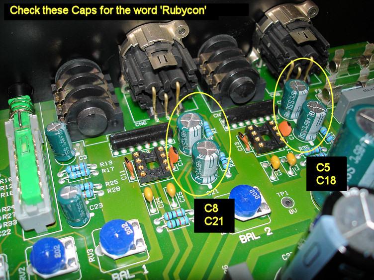
There's the 4ea 330uf Electrolytics next to the 8pin Sockets again.
If these are NOT marked as 'Rubycon', they need to be changed out with the Panasonic FC series caps.

These are the Caps that DO NOT need to be changed.
Their not in the Audio Path, and are for the 'Peak' and 'Drive' LED Circuits.
Power Supply Smoothing!!
The secret here is to get the DC voltage as clean and smooth as possible.
The cleaner the DC is, the better the Op Amp can do its job.
This Mod along with the Capacitor Mod, give about half of the 'Sonic Impact' of just changing the Op Amps out alone.
Only the 1n4004 Rectifiers in the Op Amp Power Supply are going to be changed out with HexFred Diodes.
These things are so fast on the rectifying, that they don't have any overshoot/undershoot past the 0v level.
This in turn makes the DC cleaner and less HF noise in it, which of course makes the op amps quieter.
The difference is just utterly amazing.
You need to bend the Leads as shown in the Pics for them all to fit correctly.
You also need to be sure to add the Heat Shrink Tubing over them to keep them insulted from one another.
And BE SURE to install the Diodes with the correct Polarity!!
Reference the Pics for this, and here is a link to the HexFred Data Sheet.
The Filter Caps will be changed out to Panasonic FC series, low ESR Capacitors.
The Cap Values were raised up a little to give a little extra reserve for the Op Amps when they are amplifying the Low Frequencies.
This also helps to smooth out the DC a little more.
We noticed on the O-Scope that there was an unacceptable amount of ripple on the Negative Voltage Rail.
We added this 100uf, 25v Capacitor after the IC6 Voltage Regulator to smooth it out considerably.
There were no positions to physically add it, so we made one.
Two holes need to be drilled thru the Circuit Board next to the C39 Transient Suppressor Caps Solder Pads (Reference Pics).
Then the Solder Traces were scraped on the bottom of the board near the Solder Pads to allow the new Caps leads to be soldered.
Then just install the new 100uf Capacitor in from the Top of the Circuit Board.
Be SURE to install the Capacitor with the correct Polarity!! Use the Pic as a reference.
The Negative Lead of the Capacitor MUST go towards the output pin of the 7915 Negative Voltage Regulator (IC6).
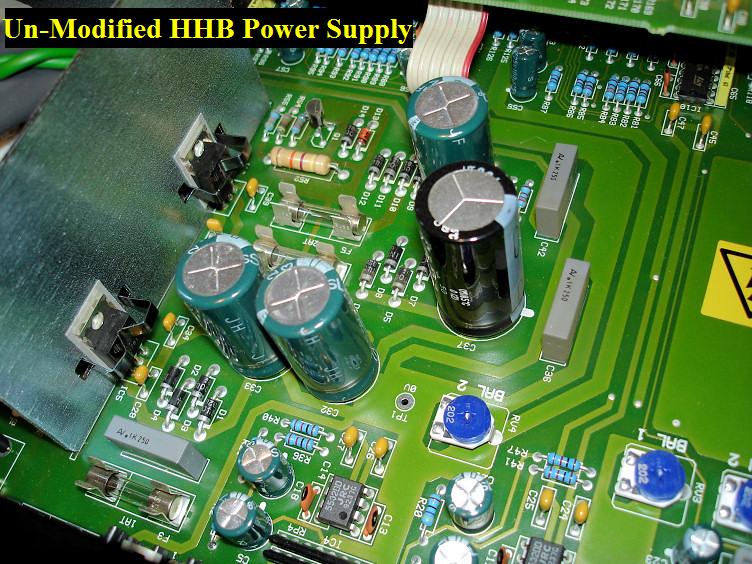
This is the Un-modified Power Supply Section.

These are the HEXFRED Rectifier Diodes.
Notice the way the leads are bent to allow proper installation into the Circuit Board.
Also notice the Heat Shrink tubing required to insulate them from one and other.
Be SURE to install the Diodes with the correct Polarity!!Here is a link to the
HexFred Data Sheet.

Here's the HEXFRED Diodes installed in the Circuit Board.
Be SURE to install the Diodes with the correct Polarity!!

We noticed on the O-Scope that there was an unacceptable amount of ripple on the Negative Voltage Rail.
We added this 100uf, 25v Capacitor after the IC6 Voltage Regulator to smooth it out considerably.
There were no positions to physically add it, so we made one.
Two holes need to be drilled thru the Circuit Board next to these Solder Pads.
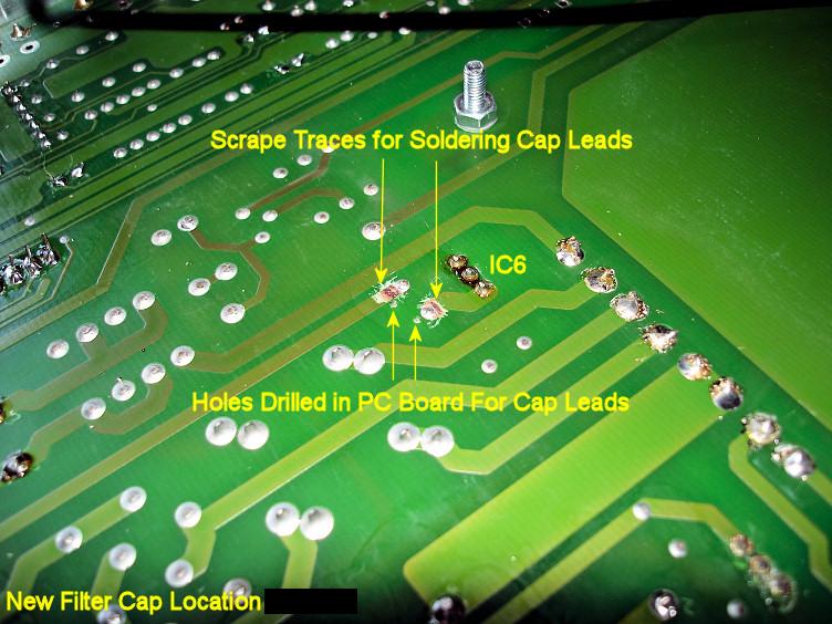
Then the Solder Traces had the Enamel Scratched Off to make room for soldering the Capacitor Leads.
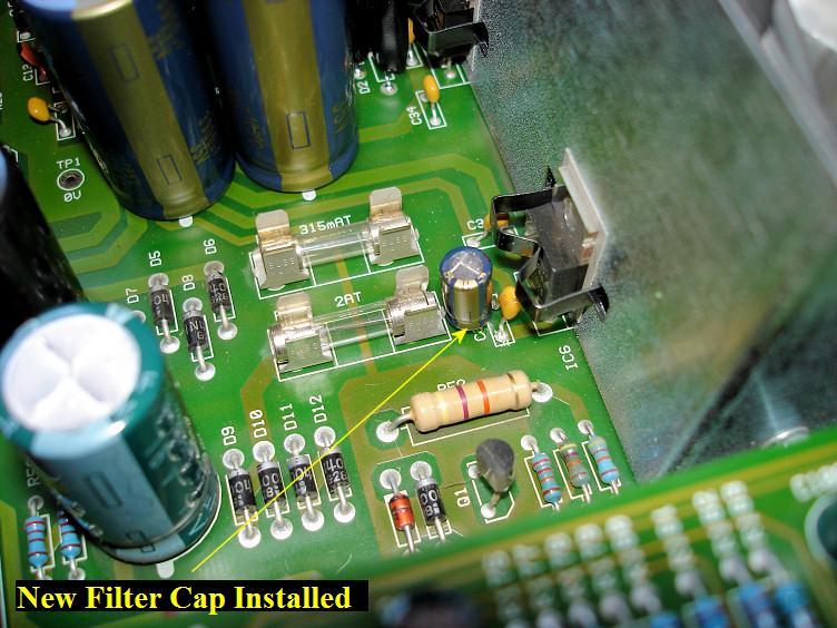
The New 100uf, 25v Filter Capacitor is added Here.
Be SURE to install the Capacitor with the correct Polarity!! Use the Pic as a reference.
The Negative Lead of the Capacitor MUST go towards the output pin of the IC6 Negative Voltage Regulator.
Mission Accomplished !!
Now Ya got a Secret Weapon for X-treme Audio!!
Take No Prisoners!
Keep Spreadin dat Voodooooo!!
"HHB Radius-20 Audio Modifications" page designed by the VOODOO GURU