  The ESSB Audio Forum Where all your Hi-Fi Audio Questions are Answered |
 |
 
  |
  The ESSB Audio Forum Where all your Hi-Fi Audio Questions are Answered |
 |
 
  |
No Foolin!!
The Low Frequencies are so Liquid and Smooth, they just FLOW from
the receiver speakers like warm Jack Daniel's on a hot summers day.
We have applied some of these modifications to the
Bellari Equipment with phenomenal results.
Triple-S Mods
Some EX3200 Discussion:
Behringer EX-3200 vs Aphex 204:
We here at the Voodoo-LABS feel that the EX3200 has more to offer because of the
way you can
manipulate the unit to give that little something special that no others
can.
First off...
You must have the Low Frequencies in your Voice Fundamental in order for
this unit to work.
If you don't have them, then the unit cannot develop the sub-harmonix
and harmonix of these base fundamental low frequencies.
It is then, a waste of money.
Second...
Most of us that use this unit, use it only for the Low Frequency
Sub-Harmonix and Harmonix generation along
with the Surround Processor
to generate a Spatial Separation of these Harmonix (ie... Hamonix
in-between Harmonix).
This is of course done by using the W5UDX Mod, which is an unbalanced
cable used to tie the
two channels together which causes the input to the Channel 2 to be inverted by the input buffer (more on this later).
The Multiband Processor section of this unit is NOT used by us.
It causes allot of noise in the final mix, and also has a tendency to
induce tearing.
We like the EX3200 because of the fact that it has the Surround Processor
option.
The Aphex units do not have this.
The Aphex makes some very nice and clean harmonix, but it doesn't have
the Spatial Enhancement that the EX3200 does.
It just doesn't have the Depth and Extension that the EX3200 has.
This fact alone makes the EX3200 the Winner.
Some EX-3200 Voodoo Theory:
Well here's the Voodoo-LABS theory on why the EX3200 works the way it does...
The Channel 1 input is injected into the unit using a Balanced XLR input.
This symmetricaly balanced signal goes thru a differential op amp
servo-buffer that
sends the waveform to the rest of the Channel 1 circuitry.
This is where the sub-harmonix and harmonix are added to the mix,
and
the Surround Processor takes a sample of this Channel 1 signal for
processing.
The signal then comes out of Channel 1 and is injected into Channel 2
using an unbalanced cable.
Using an unbalanced cable literally grounds the Non-inverting input of
the differential op amp servo-buffer,
and the signal goes to the
Inverting Input of the op amp.
This configuration now makes the Servo-Buffer an Inverting Amplifier
which actually inverts the
incoming signals harmonix 180 degrees out of
phase.
The Surround Processor circuit then takes a sample of this Channel 2
signal for processing.
The Surround Processor Spectral Enhancement circuitry tries to widen
this effect as its designed to do (see below).
But being that the Channel 2 sample is 180 degrees out of phase with the
Channel 1 signal,
the Processor actually adds or subtracts the harmonix
together.
You can adjust this harmonix 'spacing' by turning the 'Surround' control
and actually hear the
mix thickin and thin out as the harmonix phase in
and out with each other.
So this actually puts harmonix in-between harmonix!
This signal then goes thru the Channel 2 Bass Processor which gets even more sub-harmonix and harmonix added to the mix.
The Surround Processor was actually designed to give an adjustably
'wider' sound to a STEREO signal.
This is done by differentiating between the common mode signals (where the
phase and amplitude are identical in each channel)
and the Different
signals (Left and Right) in each channel.
The common mode signals are canceled out as they are not amplified,
the
Different signals (extreme Left and Right) are amplified by the
Difference amplifier op amp circuit.
This signal is then sent to an inverting circuit and then back to the
2ea channels each being out of phase set by the 'Surround' control.
So, in one direction of this control there is no center sound at all
(extreme stereo separation),
and the other direction is like a mono sound.
We are actually using this effect in a mono type situation and "tricking"
the
Surround Processor to give us fuller, thicker, more resonant Harmonix.
Well that is our Theory and We're stickin to it.
Hope that answered some of Ya'lls questions.
The EX-3200 Audio Modifications:
We here at Voodoo-LABS have done some other modifications to the EX3200
to get the best resonance and clarity out of it.
This has to do with changing out the Op Amps to a better chips with
higher bandwidth, higher slew rate, and lower noise.
That would be the Analog Devices AD823ARZ.
The ARZ is the case designator for a No Lead,Surface Mount SOIC case designation.
That's right....Surface Mount, and its rather difficult to do.
There are 16 of them that need to be changed out.
There are also allot of coupling caps that need to be changed out to
higher quality Panasonic FC series, Low ESR caps for improved audio transfer and sonic signature.
And the last mod is Power Supply improvements that help to calm the
transients,
the rectifier over/under shoot during regulation, and improved filtration.
These improvements all help to give the Op Amps the best DC Voltage for Audio Processing.
All these mods transform this Behringer EX3200 into a Super Silky Machine.
It just oozes with Liquid Voodoo.
The result is utterly amazing.
Well We hope you enjoyed our rant, now we need to go and commit MODification MADness....
MOOOO HOOOO HAAA Haaa haaaa!!!
Gotta have PARTS!!!
Triple-S Mod Parts |
||
Parts |
Part Numbers |
|
| 11ea - 100uF @ 25v Electrolytic | Digikey - P10269-ND ---- EEU-FC1E106 |
|
| 2ea - 4.7uF @ 50v Electrolytic | Digikey - P10315-ND ---- EEU-FC1H4R7 |
|
| 4ea - 2.2uF @ 50v Electrolytic | Digikey - P10313-ND ---- EEU-FC1H2R2 |
|
| 10ea - 47uF @ 50v Electrolytic | Digikey - P10321-ND ---- EEU-FC1H470 |
|
| 6ea - 10uF @ 50v Electrolytic | Digikey - P10316-ND ---- EEU-FC1H100L |
|
| 1000uF changed to 1800uF @ 35v 2ea - Electrolytic |
Digikey - P11246-ND ---- EEU-FC1V182S |
|
| 16ea - AD823ARZ SMD Op Amp IC | Digikey -AD823ARZ-ND ---- AD823ARZ |
|
| 4ea - 600V 4A Hexfred Diode Rectifier | Digikey - HFA04TB60PBF-ND ---- HFA04TB60PBF |
|
Soldering TIPS:
They're a few tricks to unsoldering SMD Op Amps that we'd like to share with you.
Tip #1:
There's a conformal coating on the surface of the PC Board to keep moisture and such from getting to the components and solder pads.
This must be removed before heat is applied.
If it isn't, then you run the risk of it flowing in with the solder and contaminating an otherwise good solder joint.
They're expensive chemicals made just for this application,
But we've been using Acetone on a Q-Tip for years with no adverse consequences.
It also works great for cleaning the Flux up after the soldering is finished.
Tip #2:
Un-Soldering can be a real pain in the butt, especially with SMD devices.
They're many special devices just for this.
The best way to remove the old Op Amps, is to take some small sharp nippers and cut each and
every one of the leads on the surface mount chip while it is still soldered to the PC board.
Make SURE all the leads are clipped, then pop the old Op Amp off the PC board.
If you leave even one of the leads connected, you will rip the circuit trace up from the board.
Then take some Fluxed Solder Braid to remove the old solder and the cut leads still on the PC Board.
Be Careful to get all the cut leads off of the board.
Then clean up the area with some acetone and a Q-tip.
Presto...the Op Amp is removed and the solder pads are clean.
If the Solder Pump gives you problems, the Solder Braid also works great on the Plated Thru holes in the circuit board.
Like were the Electrolytics are mounted.
Take a small bit of solder and "reflow" the old solder joint.
Then make the "V" with the braid, and apply the soldering iron tip. It will suck all the solder out of the hole.
Most of the time...;)
Tip #3:
For soldering we use an ultra fine tip and a thin solder.
This allows us to get in some very congested areas with the minimum of heat and solder to get the job done.
The size of the solder we use is .025" diameter flux core.
There are 16ea Op amps that were changed in this unit.
The difference was utterly just amazing.
We've listed the ones that need to be changed below,
You will see the IC identification numbers on the circuit boards.
There are 2 very hard ones to change on the Input/Output board, because they are very close to the relays.
You have to be very careful not to hit the relays with the soldering iron. It won't hurt them too badly,
but it makes for a very ugly and unprofessional looking 'Hack Job' of a mod!
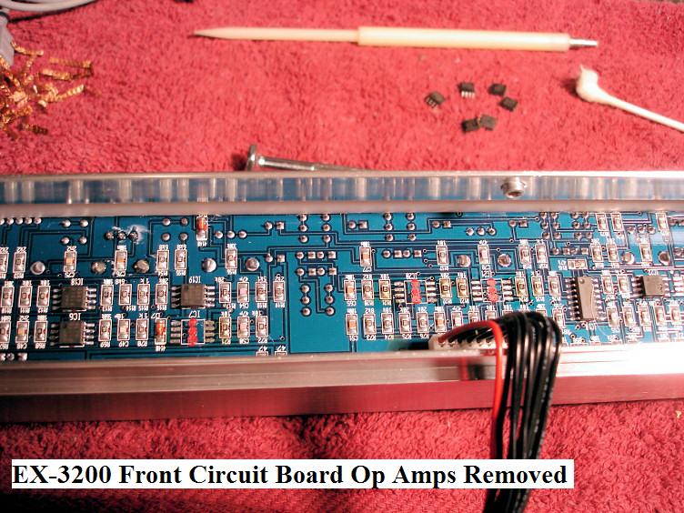
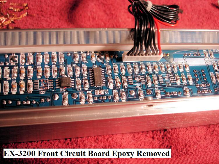
Another thing is the epoxy residue that is left on the circuit board after the Op Amp is popped off.
This must be CAREFULLY scrapped off before the new AD823 can be laid down and soldered.
If your not careful, you run the risk of damaging the traces underneath the epoxy.
Clean up the traces with some Acetone, and your ready to install the AD823's.
Be SURE to install the Op Amps with the correct Pin #1 Orientation to the Circuit Board!!
The Op Amps will have a little 'Dimple' on top of it indicating Pin #1.
The Circuit Board will usually show a 'Dip' at one end of the PC Board Silkscreen for the IC Pin #1 indication.
Just match the two up.
Here is the list of IC's that need to be changed:
IC3, IC4, IC5, IC6, IC7, IC8, IC9, IC17, IC18, IC19, IC20, IC21, IC22, IC23, IC24, IC25
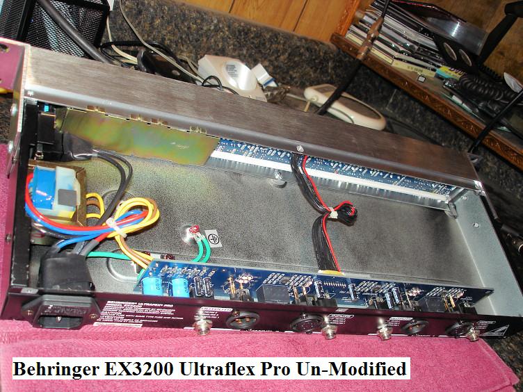
Its best to remove the boards completely from the unit.
This is not hard. Just go slow and be aware of what needs to happen before you do it.
Remove all the knobs, and the Metal Shield just 'pops' off.
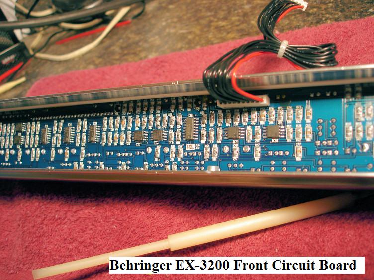
The Front Circuit Board is held in place by two rubber strips. Note how they are oriented before you pull them out.
When you reinstall them, just use some RTV Clear Silicone to hold them in place.
You will more than likely need to Re-EQ after this mod, because it changes the Sonic Characteristics that much.
Also the Rack Gear Gain structure will more then likely have to be re-adjusted.

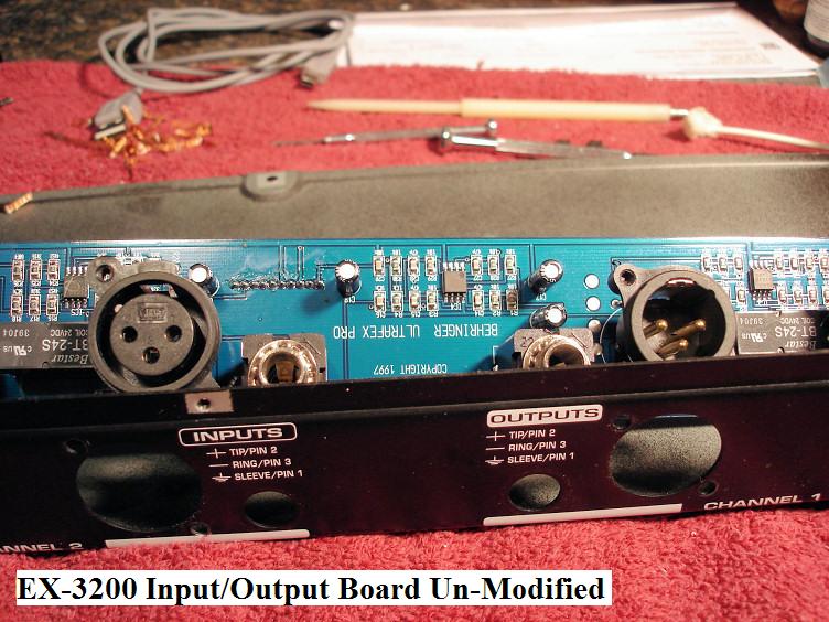


We didn't get elaborate with the info and Capacitor #'s here because you will be changing all but 2 of them.
Just be sure to note the Polarity of the ones you are removing.
DO NOT CHANGE the .22uf 50V caps as there is no substitute in the Panasonic FC series.
These capacitors are identified as C93 and C100 located on the Front Circuit Board.
It's best to do just one Capacitor Value Range at a time, that way you don't have to remember where and what.
It's really just a matter of unsoldering and removing the old capacitors, and installing the new ones.
The sizes are close to the same so they should fit with no problems.
No surprises here.
But Be sure to install the Capacitors with the correct Polarity!!
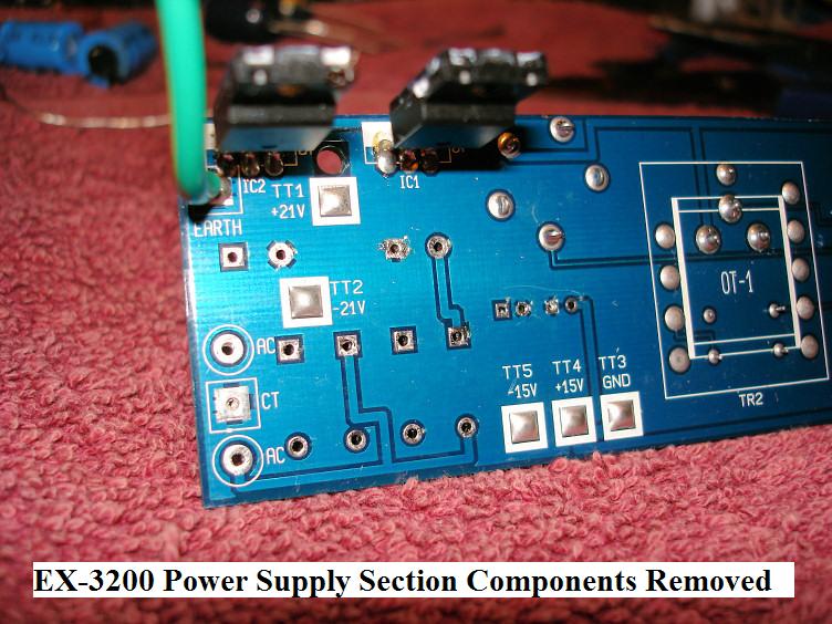
Power Supply Smoothing!!
The secret here is to get the DC voltage as clean and smooth as possible.


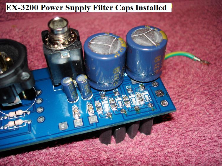


Yer Done!!
Now Ya got that Super Silky Secret Smooooooth Audio!!
There's nothing like it!
Ya'll Take Care now....Hear!
Click here to Return to the Top of this Page.
Click here to Return to the Gearslutz Voodoo Audio Mods Page.
Click here to Return to the Home Page.