  The ESSB Audio Forum Where all your Hi-Fi Audio Questions are Answered |
 |
 
  |
The ESSB Audio Forum Where all your Hi-Fi Audio Questions are Answered |
|
|
- Mod Notes -
They're a few other things We would like to say.
Difficulty -
First, these mods aren't all that easy if you've never had any SMD (Surface Mount Device) experience.
You run the risk of lifting circuit traces, overheating components, damaging ESD sensitive devices, and such.
Kenwood epoxies there chip components to the circuit boards with glue.
This makes it that much more difficult to desolder and remove these components without damaging the surrounding items.
It takes time, equipment, and patience to do it correctly.
Changing Tantalums and Ceramic Chips with Electrolytics -
What we did was replace the Tantalums (and some other chip caps) with High Grade Panasonic Low ESR Electrolytic Capacitors.
The problem with that is, since the Tantalums are on the bottom of the boards, there's no room for the electrolytics there.
The solution is to carefully drill holes thru the PC board to allow the leads to go thru from the other side.
This makes the mods more time consuming and dangerous.
You have to be aware of the circuit traces on the other side of the board before you drill.
Sometimes you will be drilling thru the Ground Plane on the opposite side,
this requires counter boring to keep the penetrating leads from touching the ground plane.
OK,
Lets get to work.
Bring out the Torture Devices!!!
IF Unit (X48-3100-00)
Circuit Description:
Sub-Receiver/Monitor
The TS-950sdx has a completely isolated Sub-Receiver which is independent of the Main Receiver.
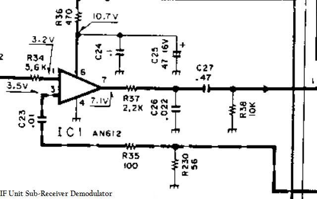
It uses a 10.695Mc IF for the IF Filters, then the IF signal is demodulated by the AN612 Product Detector (IC1).
The resulting low level AF signal leaves the Product Detector IC and goes thru a RC Low Pass Filter consisting of R37 and C26.
The cut off frequency is around 3.2Kc. This is unacceptable.
We will be changing the value of C26 from .022uF to .0068uF. This will give us a new cut off frequency of around 15Kc
The AF signal then goes thru a RC High Pass Filter consisting of R38 and C27.
This rolls off the low frequencies pretty bad by the time it gets to around 34cps. This is also unacceptable.
We will be changing the value of C27 from .47uF to 10uF.
This will drop the cutoff frequency to around 10cps.
The Sub-Receiver/Monitor AF Signal then continues on to the AF Unit for Pre-amplification.
Monitor Circuit:
The Monitor circuit is actually the Sub-Receiver.
It is enabled during xmit, and the 10.695Mc IF Filters are bypassed. So the full audio spectrum is actually received.
Here's the Parts!!
IF Unit (X48-3100-00) Mod Parts |
||
Capacitor Value Changes: |
DigiKey - Part Numbers - Panasonic |
|
| C26 - .022uF changed to .0068uF 805 SMD |
PCC682BNCT-ND ---- ECJ-2VB1H682K |
|
| C27 - .47uF changed to 10uF 1206 SMD Chip to Electrolytic |
P10316-ND ---- EEU-FC1H100L |
|
Yer gunna have to get to the boards and remove them from the radio in order to do these modifications.
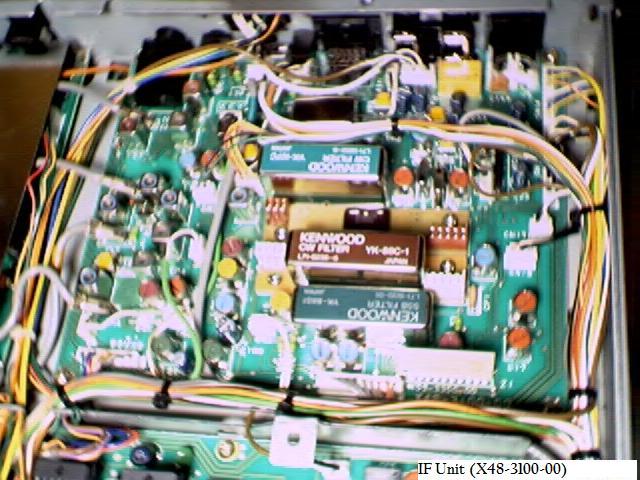
The IF unit is located on the bottom of the radio.
To access it, Very carefully turn the TS-950SDX upside-down. The DSP Unit (normally on the bottom) will be on the top now.
Squeeze the DSP Cable connectors and carefully jiggle them while pulling to disconnect them from the back of the rig.
Remove the 14ea countersunk screws from the bottom cover, then remove it.
This will expose the inside of the rig. You will see 4ea circuit boards side by side.
With the front of the rig facing you, the IF Unit is the circuit board on the right, furthest from you. See Pic.
IF Unit Removal:
This IF Board needs to be removed.
We found it's best to remove the Cable Connectors first, before the screws are removed.
It might be helpful to take a picture of it, or to label the connectors to aid in reinstallation.
To remove the Cable Connectors, it takes a gentle but firm touch.
Grab the wires next to the connector and lightly pull on it while gently rocking the connector back and forth.
Do this while simultaneously holding the printed circuit board down.
Be very careful not to get to rough with them. You don't want to pull or push too hard, this stuff is fragile.
Remove the screws holding the circuit board in the chassis.
There is also a black screw on the back of the sdx, in between all the Phono jacks.
Gently wiggle the board out from under the wire bundles and structure.
IF Unit MODification
Now that ya got the IF board out and on the bench, ya got all your parts, looks like yer ready to commit Sacrilege.
This board is the easiest to mod. Just 2ea components to change.
Tip #1:
There's a conformal coating on the surface of the PC Board to keep moisture and such from getting to the components and solder pads.
This must be removed before heat is applied.
If it isn't, then you run the risk of it flowing in with the solder and contaminating an otherwise good solder joint.
They're expensive chemicals made just for this application, But we've been using Acetone on a Q-Tip for years with no adverse consequences.
It also works great for cleaning the Flux up after the soldering is finished.
Tip #2:
Un-Soldering can be a real pain in the butt.
They're many special devices just for this.
The thing we use the most of is Fluxed Solder Braid.
This stuff is worth Gold, especially when working with SMD stuff.
We usually fold it in a "V" shape and place it on one side of the SMD solder pad.
Then the soldering iron tip is placed in the "V" and pushed against the solder joint.
Presto...the solder is gone. Then the other side is done.
The SMD will still be stuck there because it is Epoxy Glued in place.
Most of the time when unsoldering the other side of the SMD, while its still hot, you can "flip" it up with the soldering iron tip.
You have to be sure all the solder is gone, cause if it aighnt, you'll lift the solder pad.
One friend of ours says he just takes nippers and crushes the center of the old SMD component while
its still soldered on the board, then unsolders the ends.
Solder Braid also works great on the Plated Thru holes in the circuit board. Like were the Electrolytics are mounted.
Take a small bit of solder and "reflow" the old solder joint.
Then make the "V" with the braid, and apply the soldering iron tip. It will suck all the solder out of the hole.
Most of the time...;)
Tip #3:
For soldering we use an ultra fine tip and a thin solder.
This allows us to get in some very congested areas with the minimum of heat and solder to get the job done.
The size of the solder we use is .025" diameter flux core.
SMD Chip Caps:
These are a little difficult to identify. The board isn't marked for these items.
We have added some pics to help you find them.
Removal and Installation is also a little tricky, especially for beginners.
C27 is of a special installation and will be described in-depth below.
See the pictures below for the locations.
| C26 - .022uF | - Change this to a .0068uf |
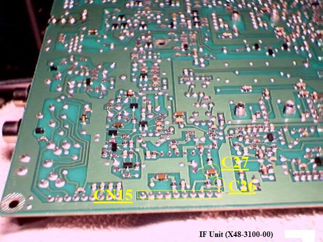
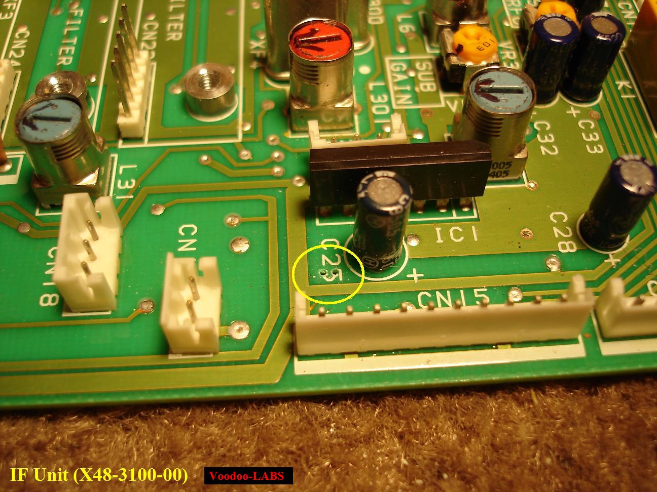
Here is a Pic of the bottom of the IF Unit. The Caps to be changed are marked in yellow.
Notice the reference of CN15 to help locate the capacitors.
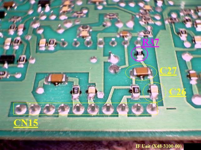
Here is a close up of C26 and C27.
Changing SMD Chip Cap C27:
Reference the pictures below to change C27 to a 10uF Electrolytic cap.
When installing the Electrolytic, the "+" terminal must be installed towards R37!!
| C27 = .022uF | - Change this to a 10uF Electrolytic |
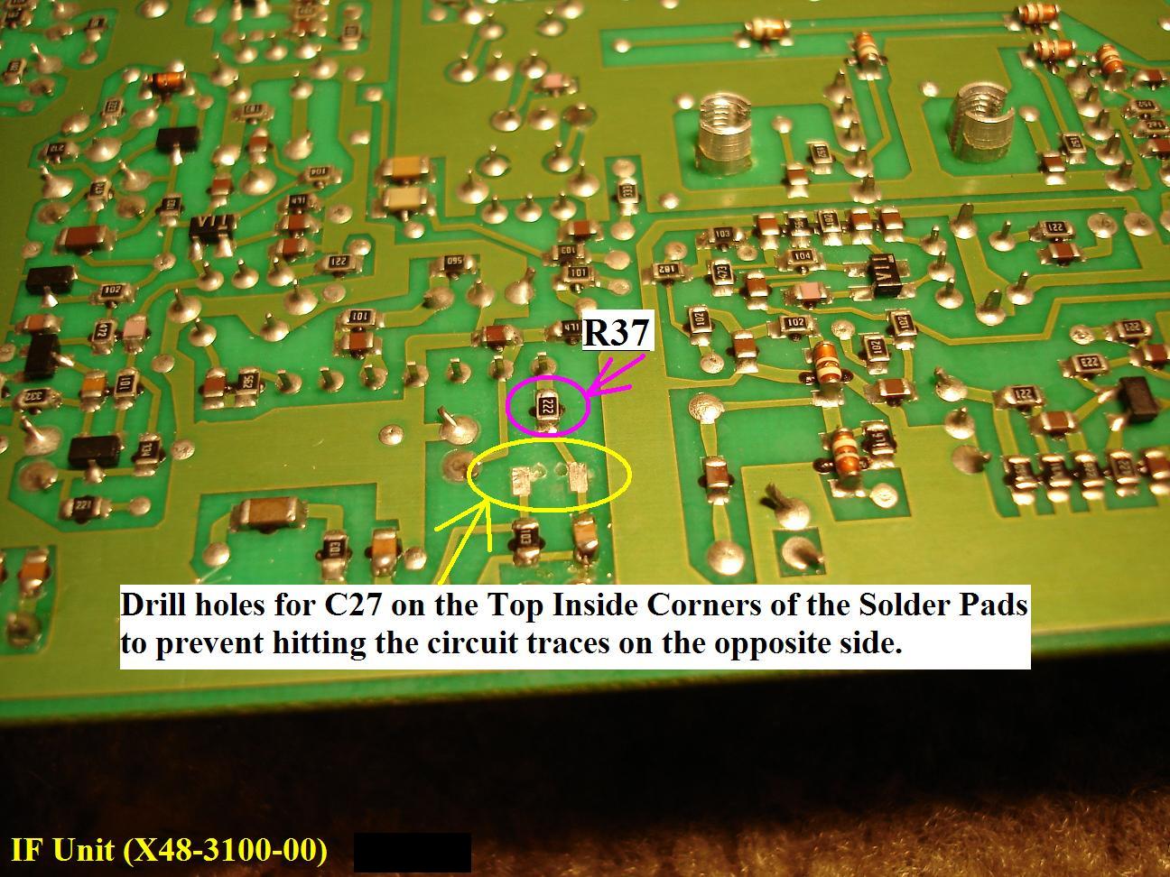
This Pic shows the were to drill the Holes thru the Board. They are marked in Yellow.
It is best to use a Pin Vise with a very small Drill bit. We used a .027" bit.
Here's a pic showing the other side of the IF board were the holes come thru.
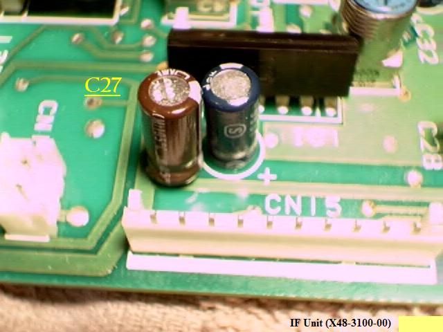
Here the new Electrolytic is installed.
While Soldering, be sure to raise the cap up a little from the board so it won't touch.
We'd say about 1/16" or so clearance.
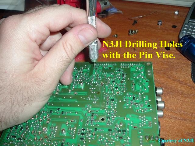
Here is N3JI demonstrating the use of the Pen Vise.
Ground Loop Prevention:
We have noticed a low level 60Hz hum present in the Audio from the TS-950SDX.
This hum is present in all the Audio Outputs in various degrees, mostly due to ground loops.
We have tracked all of them down and thier preventative measures can be seen at Hum-Noise-Cable Reroute Mods.
We have added the fix for the IF Unit here since you already have this board removed.
The fix for the IF Unit is to isolate 3ea Ground Traces from CN15 as shown in the picture below.
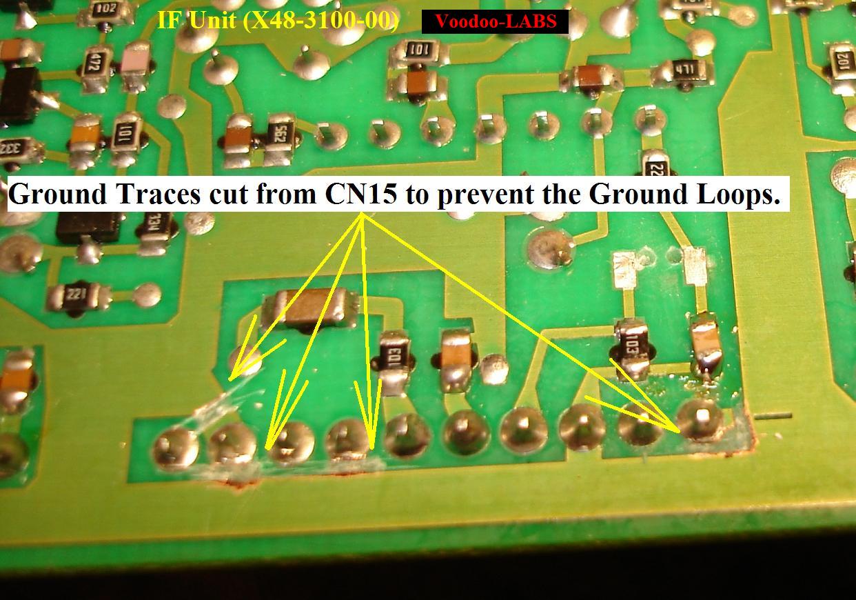
Cut the Ground Traces form CN15 as shown in the picture above.
IF Unit Re-Installation
OK...
Before you attempt to re-install the IF Unit, take the time to look over the board extremely well.
Be sure all the Flux from your soldering is cleaned up.
Look for any accidental solder bridges that might have happened while you were soldering.
Be sure all the cut leads from the installed components are not "stuck" on the board anywhere.
Give it a good inspection.
IF Unit Installation:
It is basically just the opposite of the removal.
We found it's best to install the screws first before the Cable Connectors are reattached.
Use the pictures you took of it, or the labeled connectors to aid in reinstallation.
To install the Cable Connectors, again, it takes a gentle but firm touch.
Line up the connector and gently push down on it until it snaps into place.
Do this cautiously, because if you push too hard, you run the risk of cracking the PC Board.
NOTE:
We would suggest that you re-install the covers and try the rig out now, before any other modifications.
Do this after each board is modified. This will help you isolate any problems that you might have.
If you modify all the boards at the same time and then have problems it will be more difficult to troubleshoot and fix!
Great!!
You've just committed a Violation on Kenwood's Elite!!
The Kenwood Purists will hunt you down!
....geeez...tell 'em to get a life....
Click here to Return to the Top of this Page.
Click here to Return to the TS-950SDX Receiver Mods Page.
Click here to Return to the TS-950SDX Voodoo Mods Page.
Click here to Return to the Home Page.
"TS-950sdx AF Unit Mod" page designed by the VOODOO GURU